November 2021
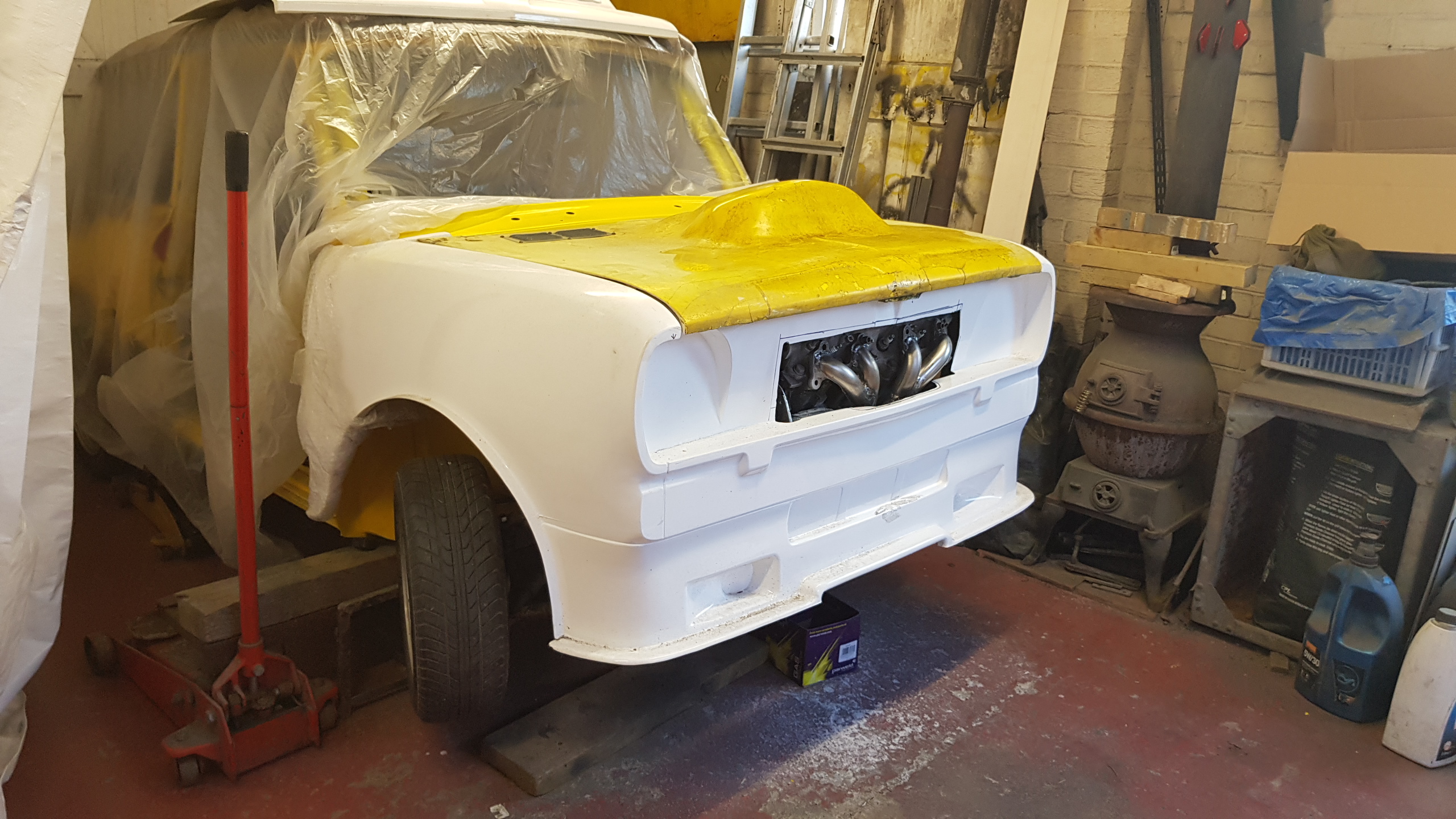
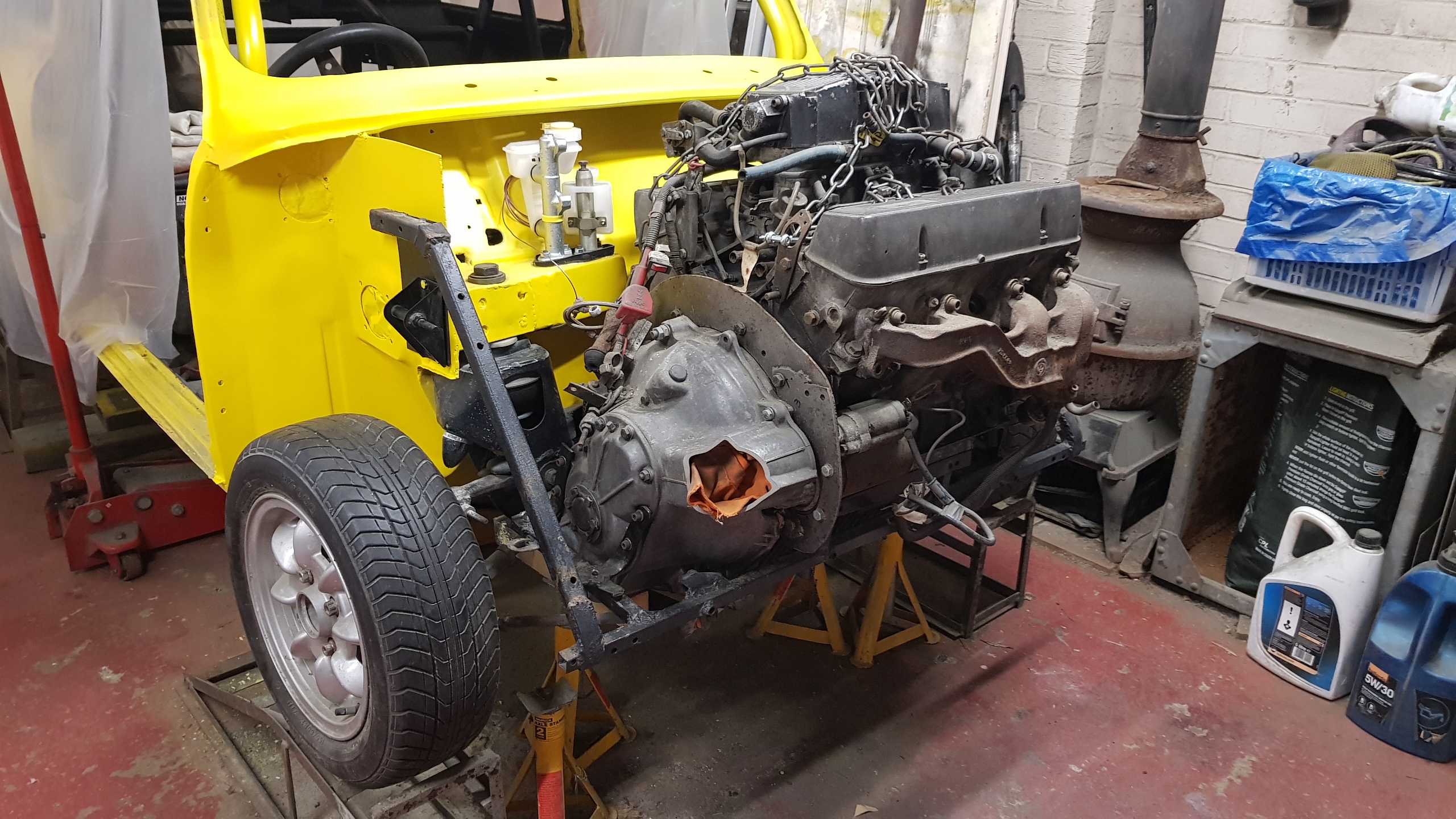
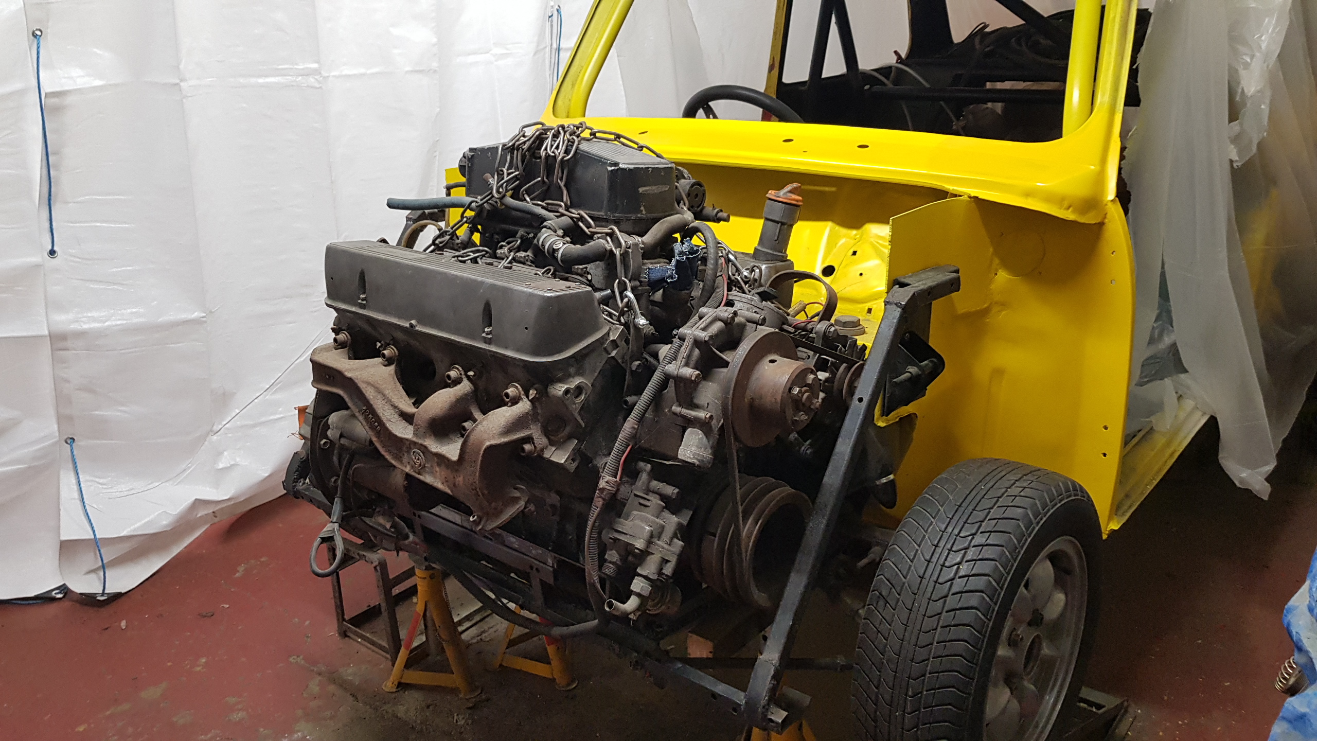
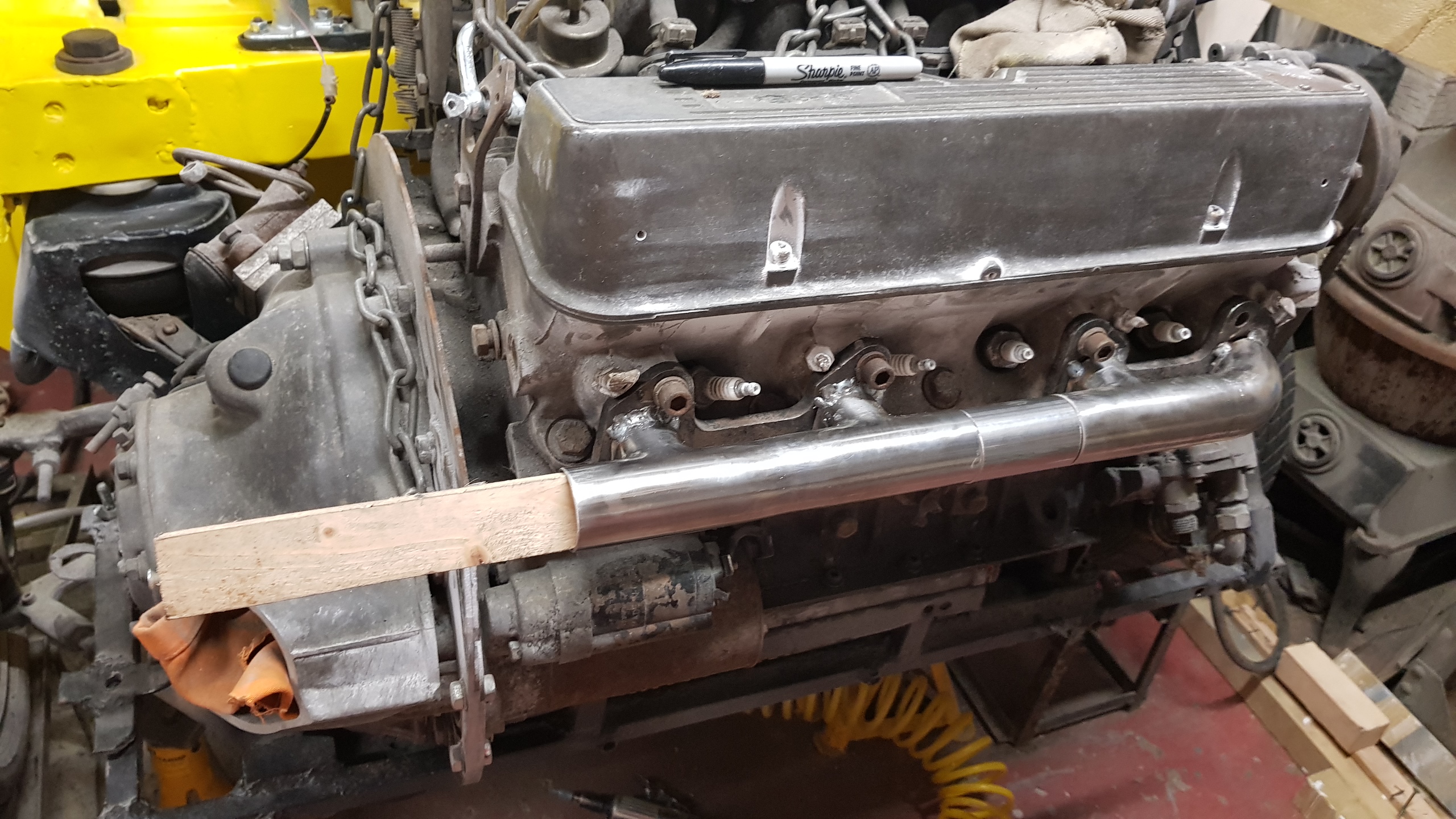
Front end painting is sort of done enough for now, so time to throw the
engine in and start looking at the rationalising the package a bit.
I'm wondering if we can make space for a decent front mounted radiator so we
can do away with the one in the boot., if not, then perhaps a decent modern
radiator in the boot means we won't need one at the front?
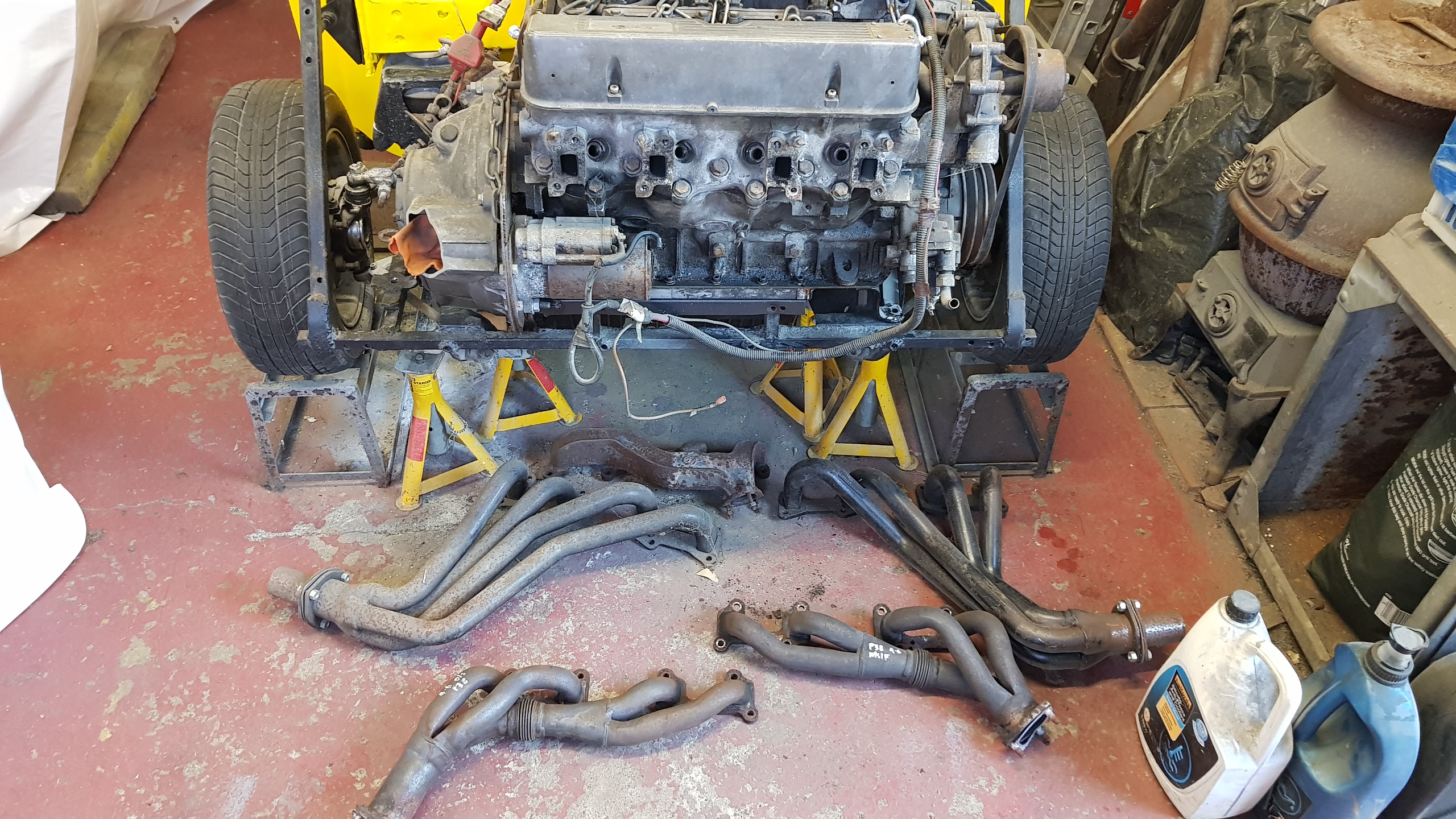
Maybe the big ugly cast manifold can be replaced with simple tubular log that exits over the bellhousing before heading downwards? That would free up a decent rectangle of space from the starter motor to the NST wheel...
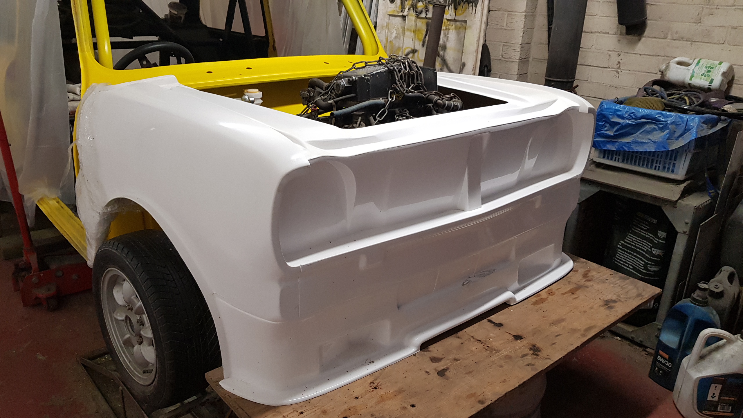
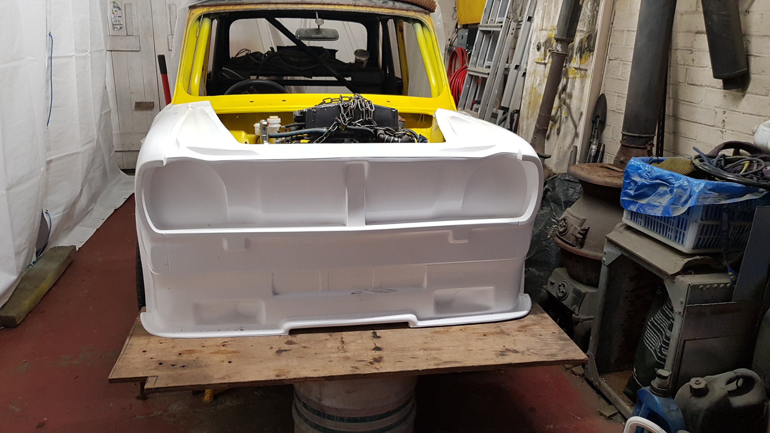
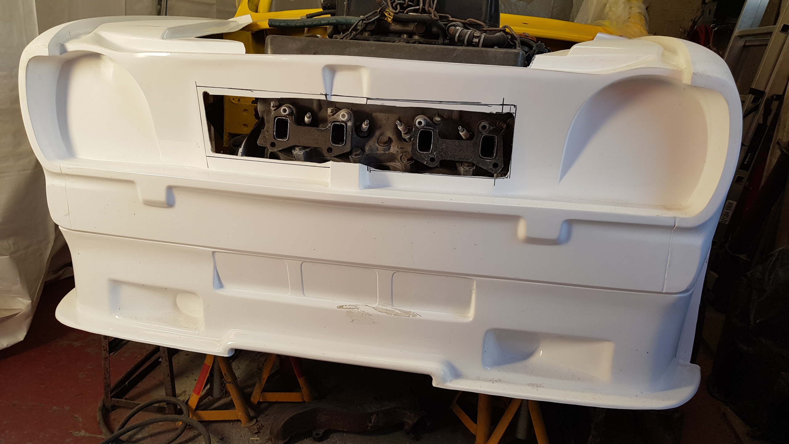
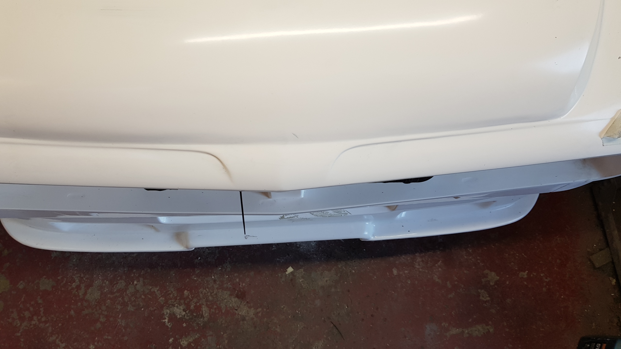
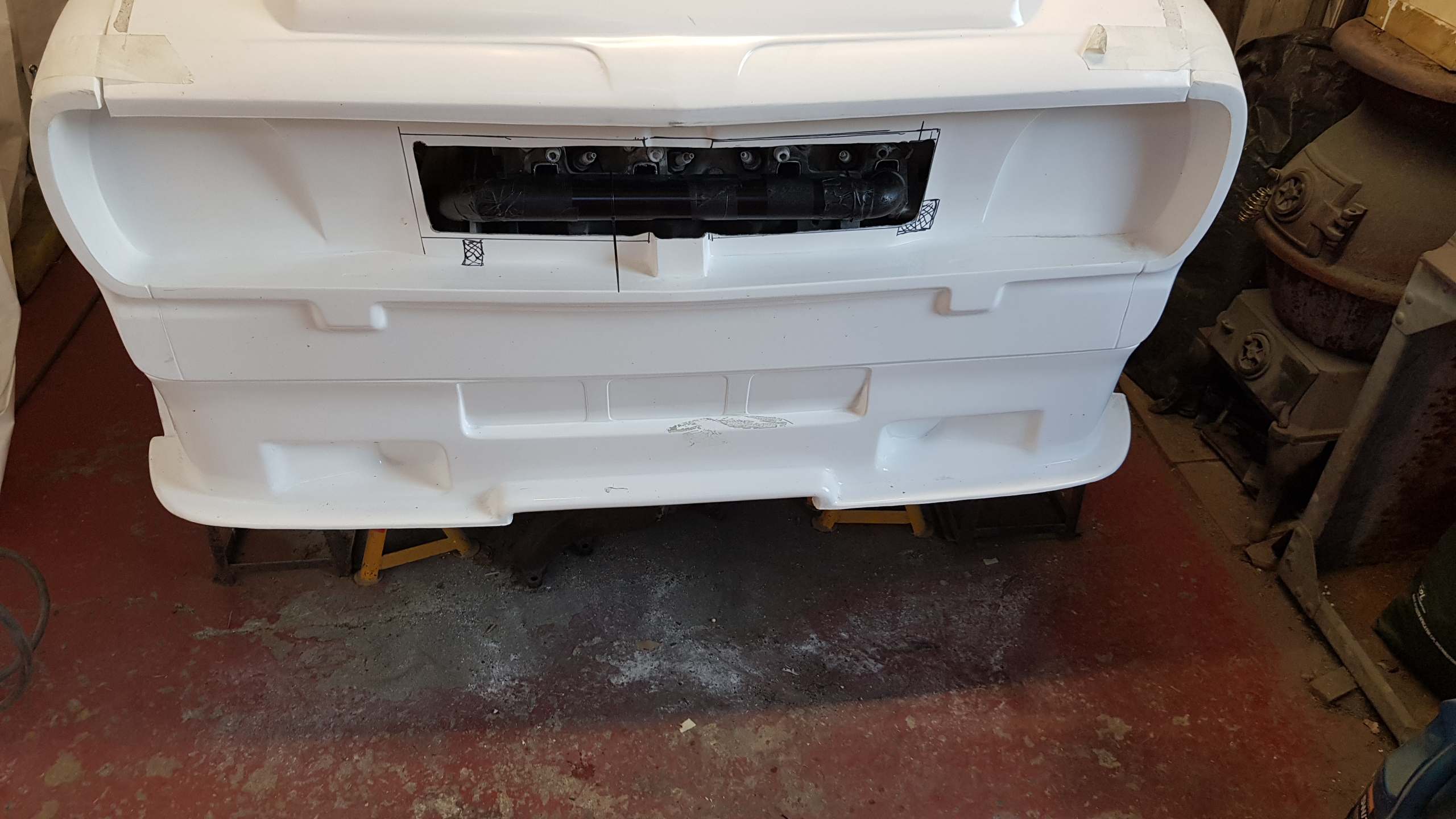
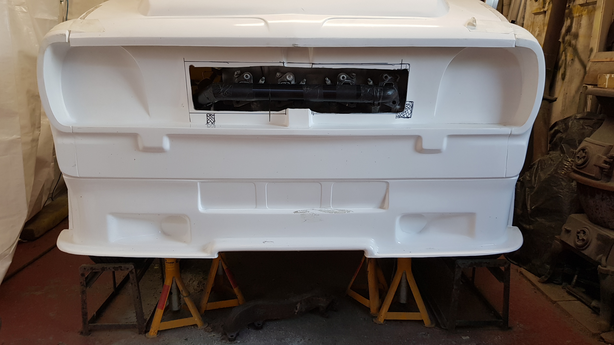
The new flip front balanced in place to get a feel for what space we have inside.

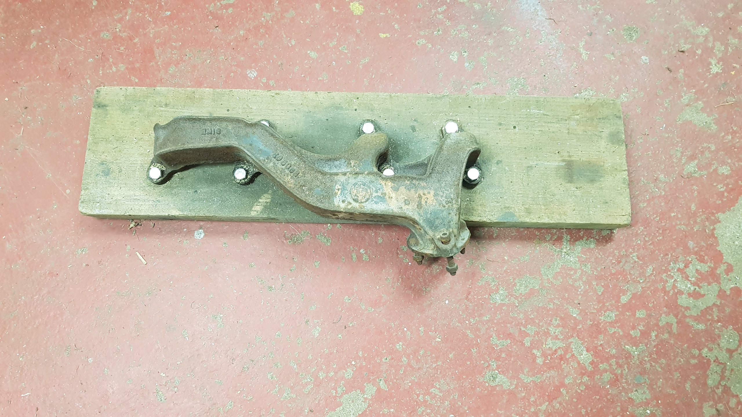
Time to look at the spare manifolds and decide what to chop up. Lets start with some flanges!
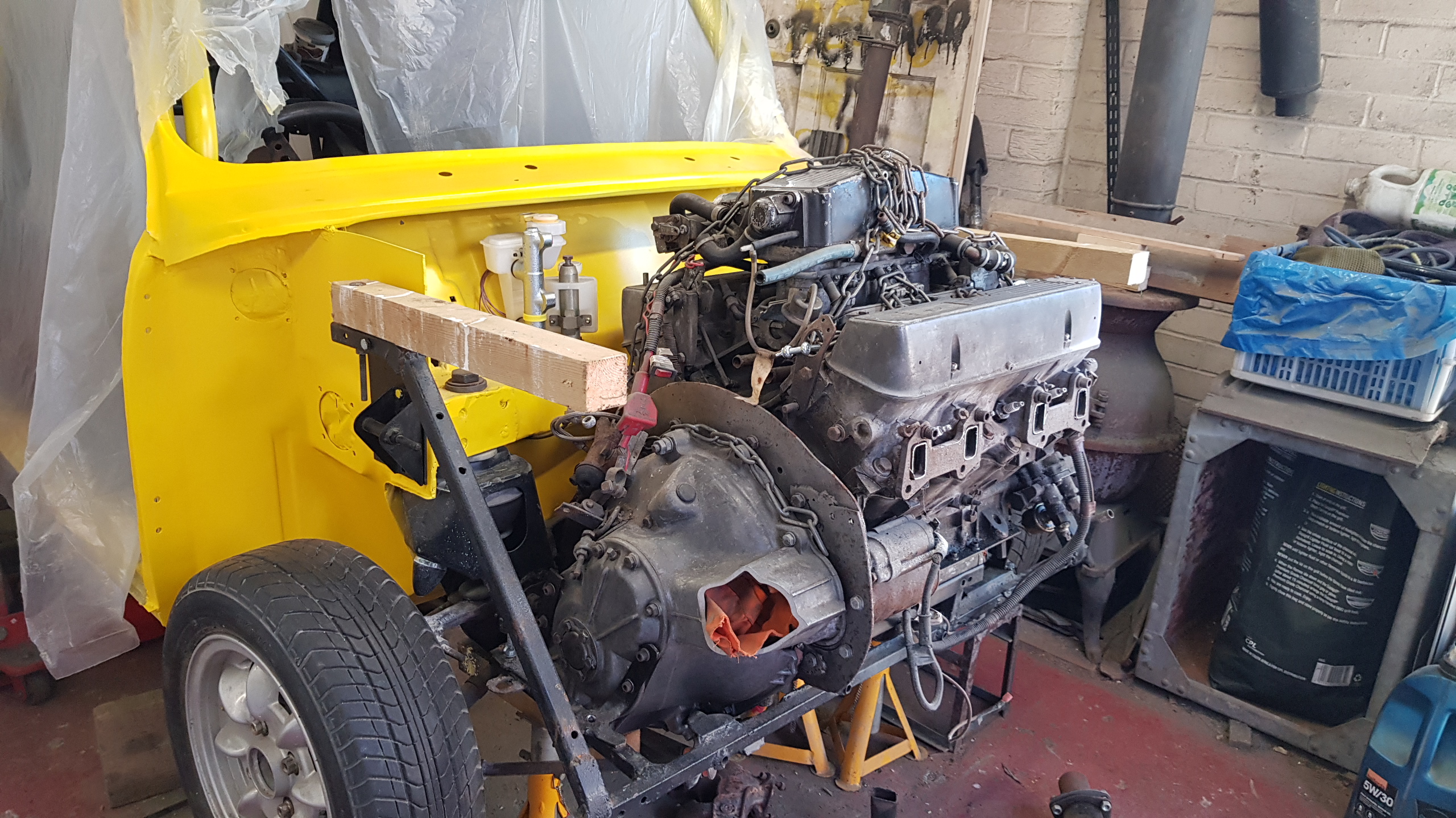
On with some temporary, yet magically adjustable brackets brackets to hold the front in place.
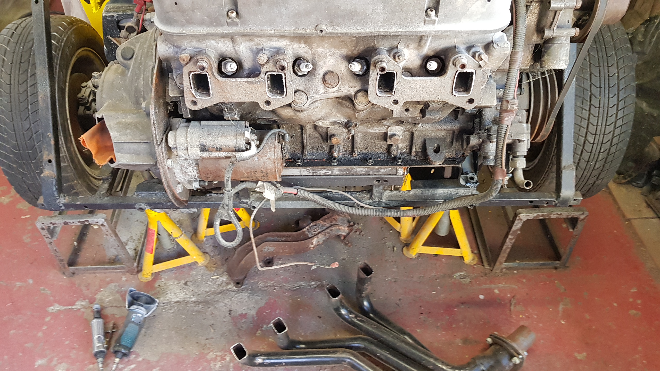
Mild chopping to miss the rocker cover and make space for the manifold.

Now children, with just a gas pipe elbow, some bits of wood and some tape, we can build a prototype...
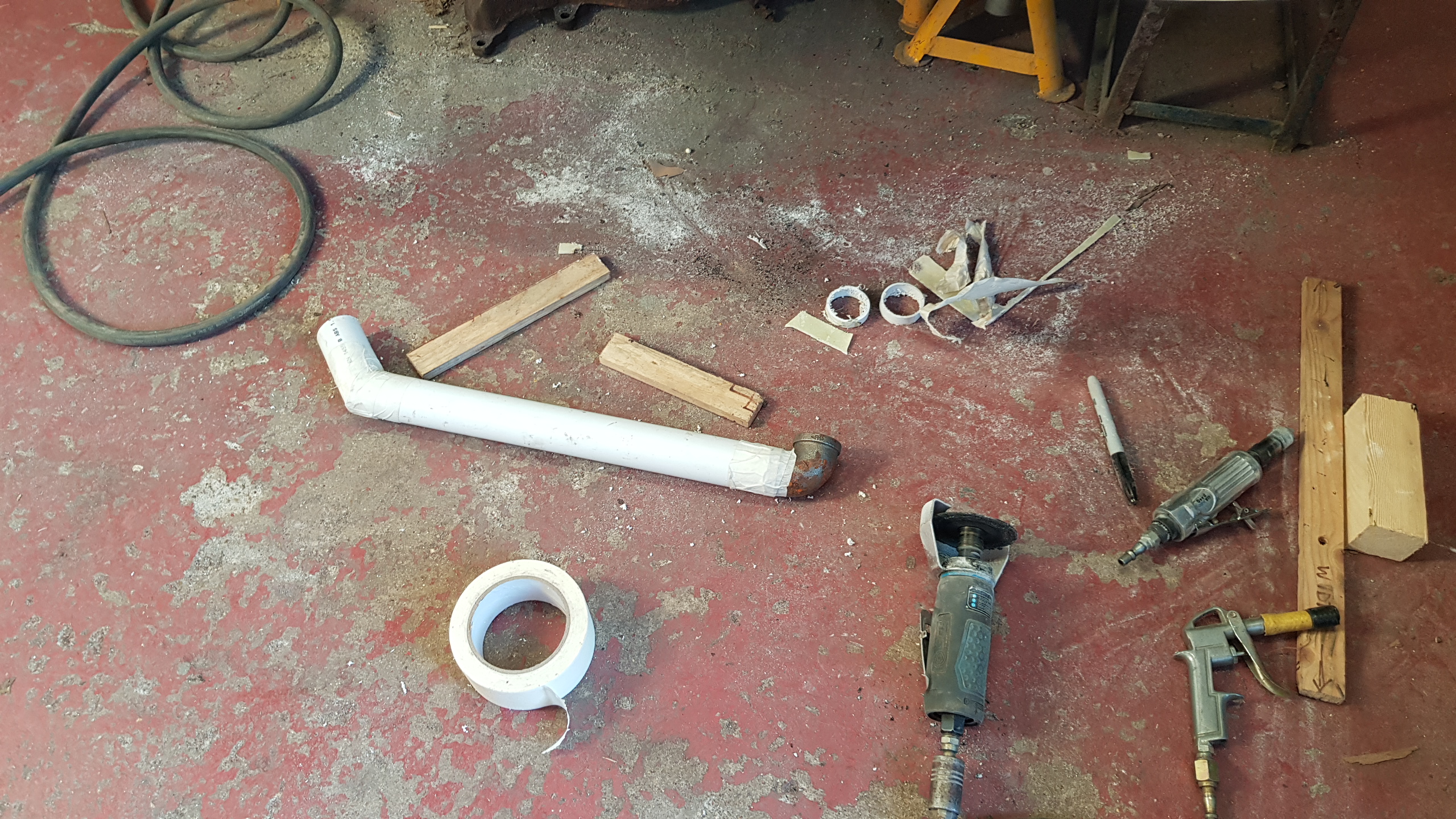
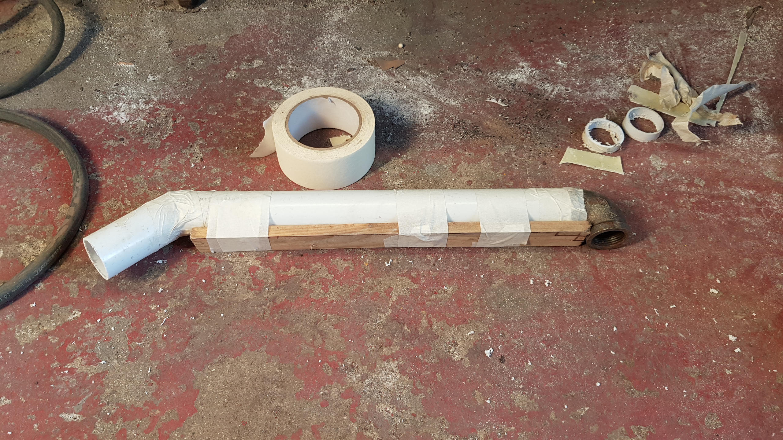
Sort of fits as a proof of concept!

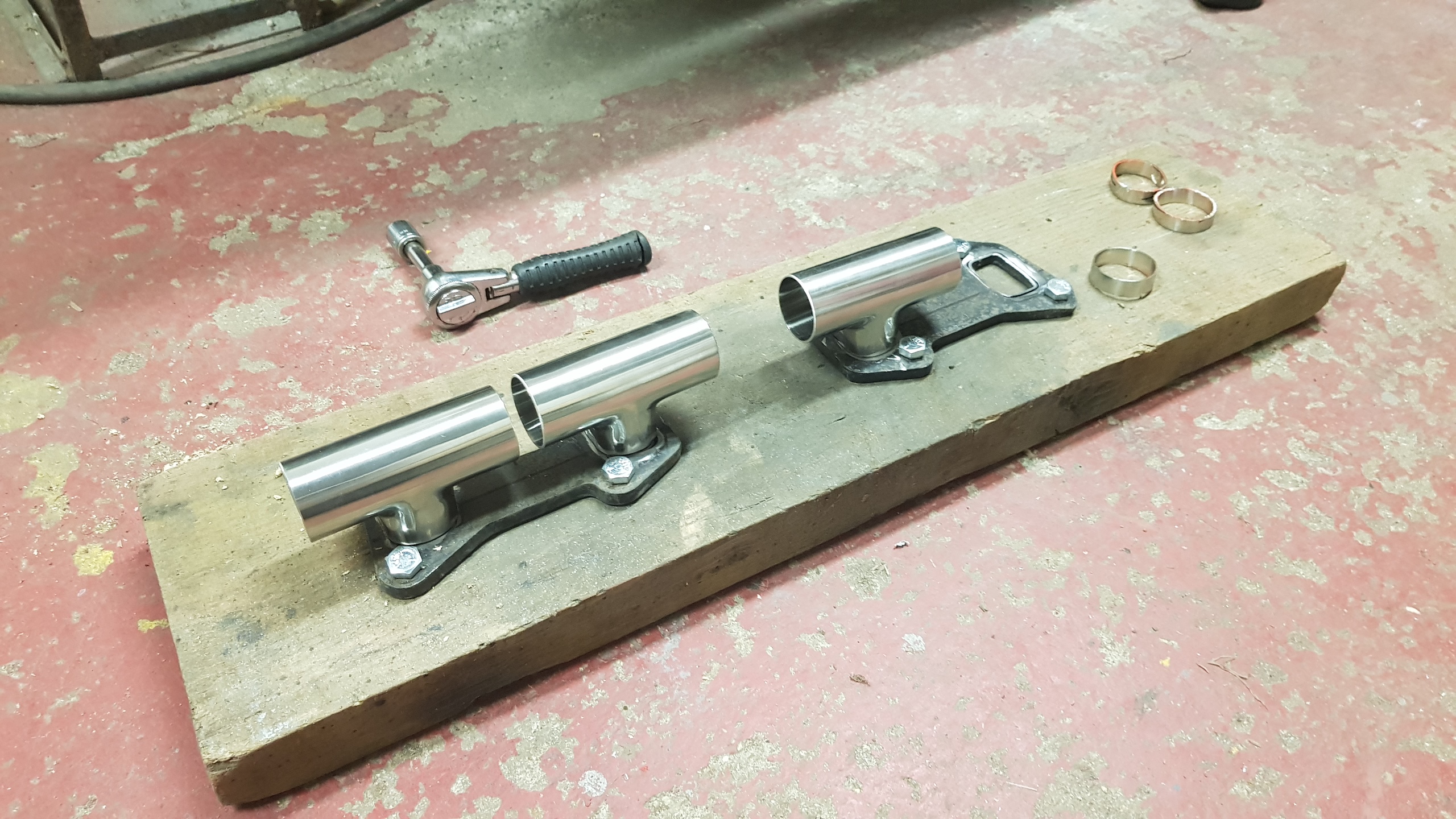
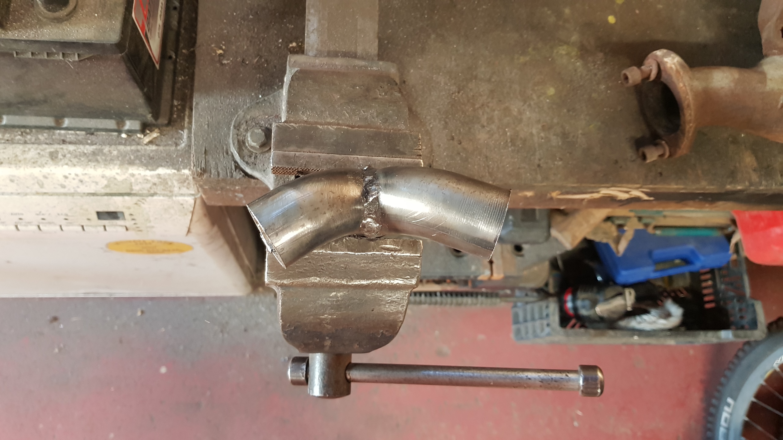
I got me some 38mm stainless dairy pipe looks perfect for a test build.

Using the old manifold as a template to make some bolt holes.
Flanges bolted in place on the jig with shortened T pieces in place.
The offcuts look to be approximately exactly the right length to fill up the small gaps !
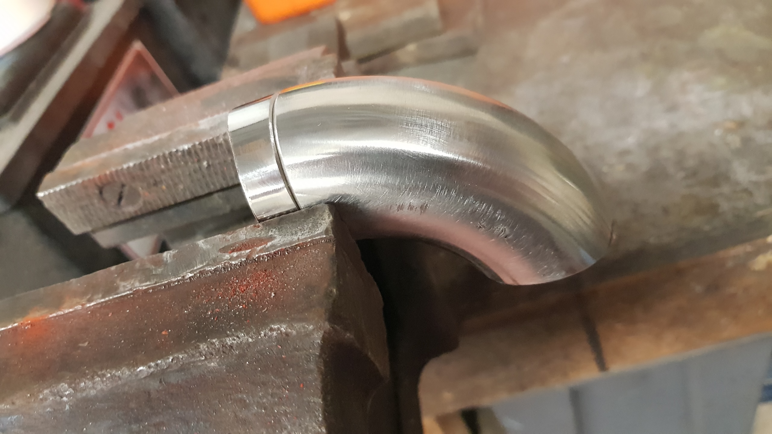
First bit of gluing underway. The 12x33 'bit-o-wood' is a nice tight fit inside the pipe so keeps things in line during welding, with only minimal smoke.

Sort of fits. (Yes I know there's still a gap).
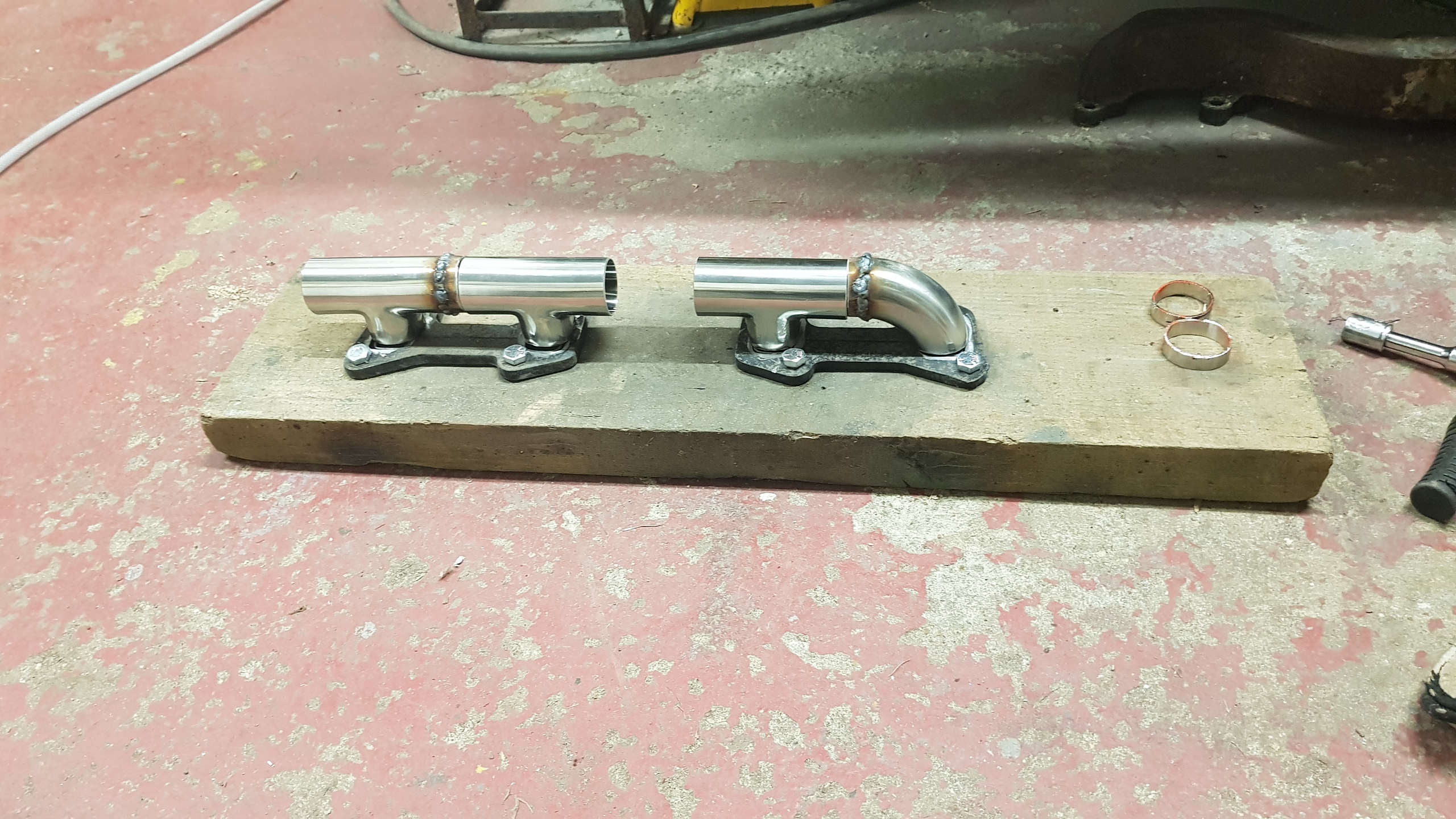
The 'bit-o-wood' alignment system strikes again!
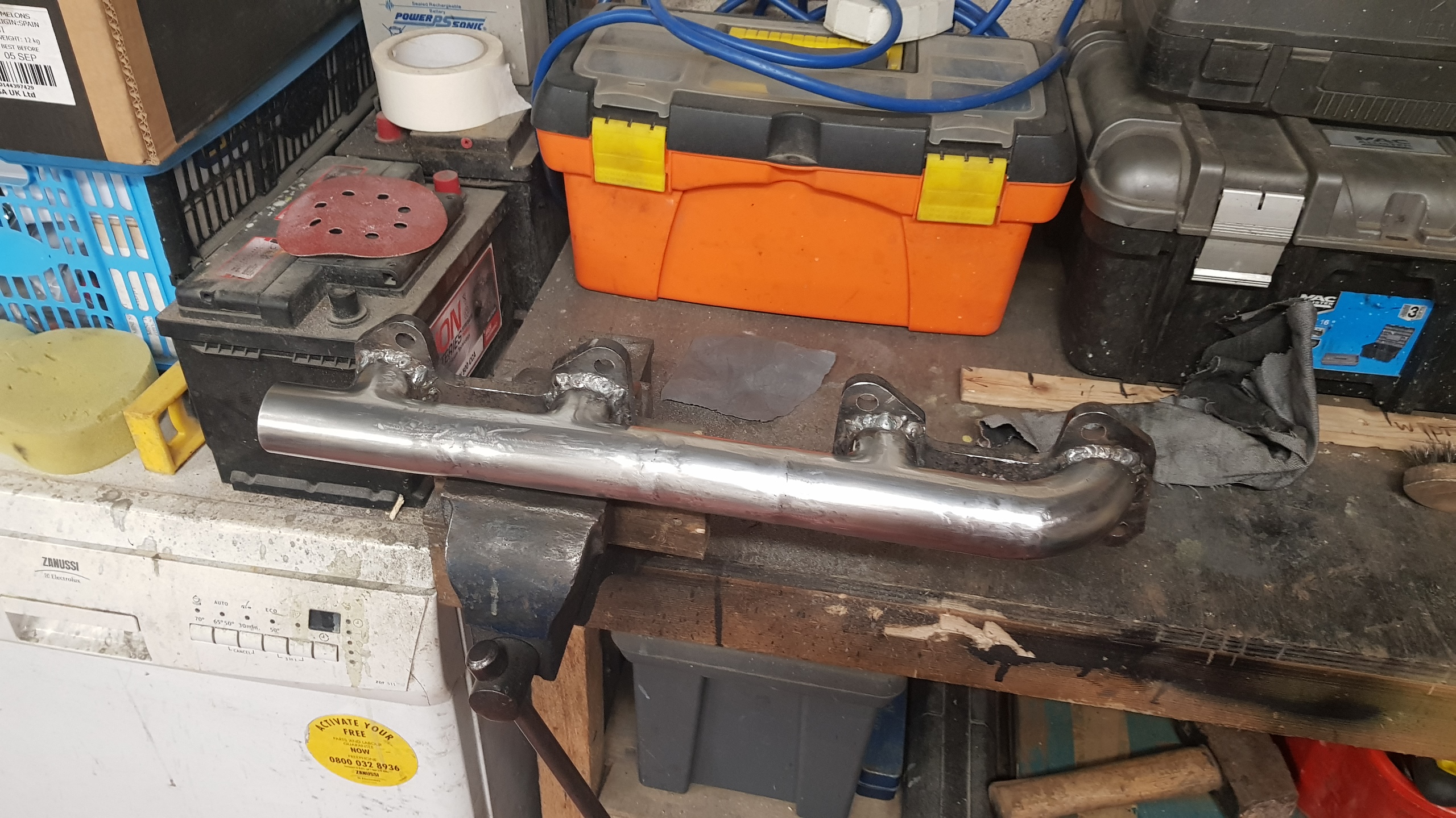
Roughly bodged together.
After a bit of time cleaning things up it's almost looking presentable!
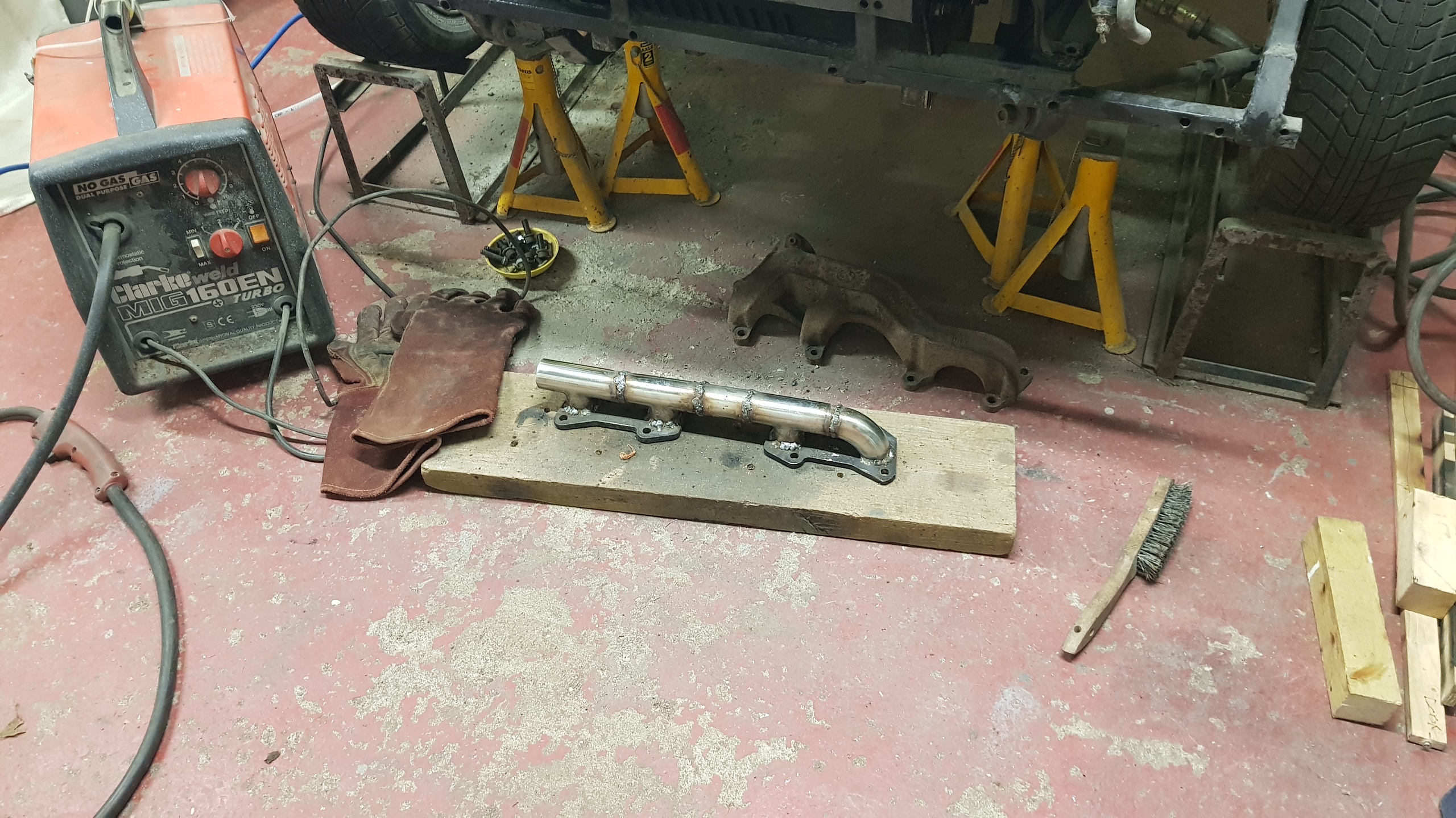
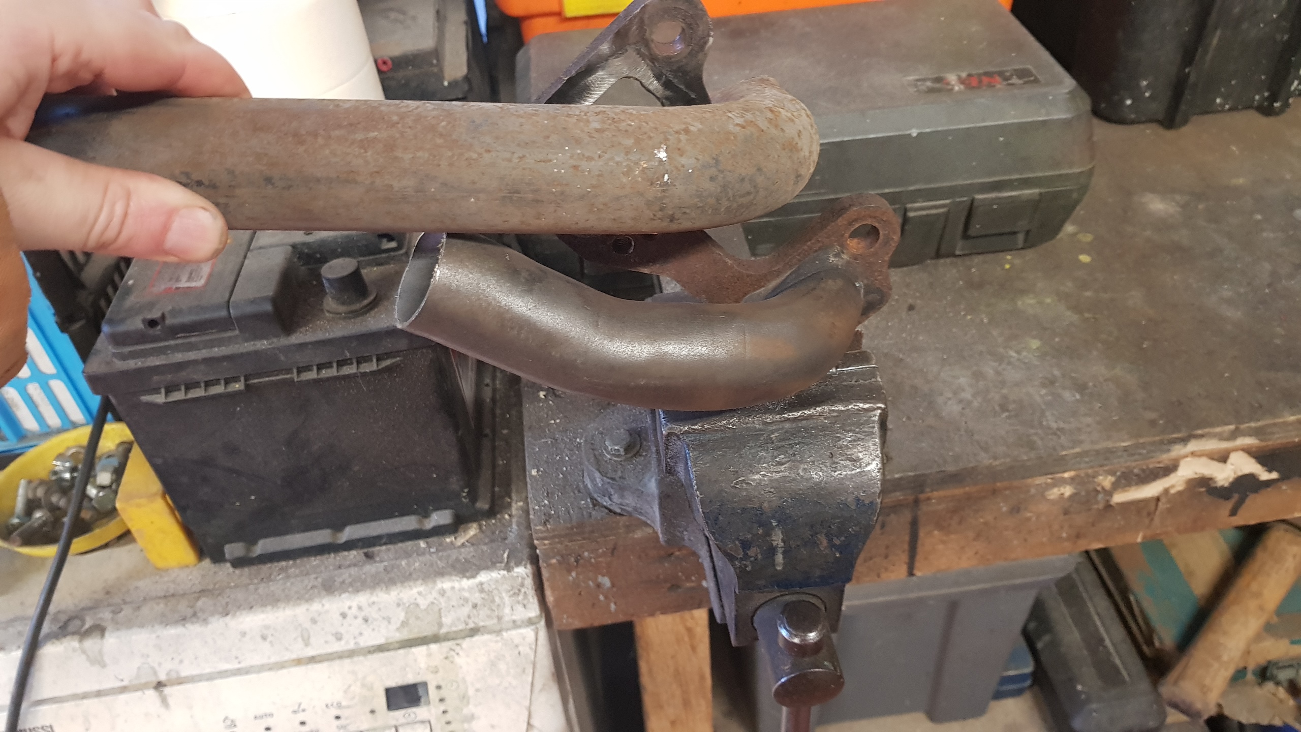
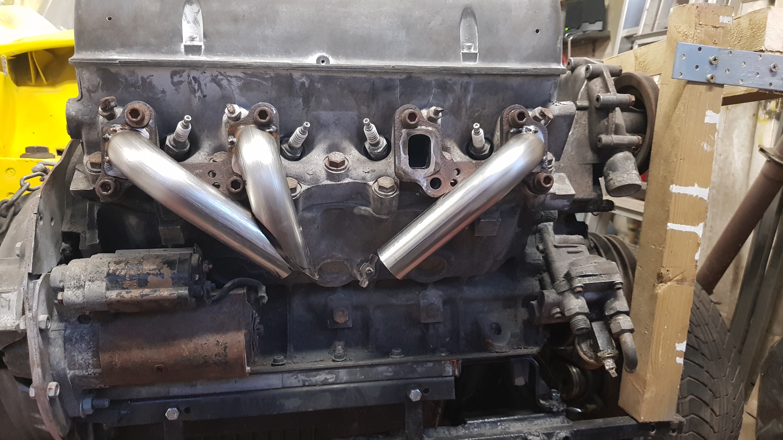
After the fun of the log manifold, I thought it could be entertaining to try to do something with a little more flow that would fit the rear bank, in place of the heavy cast manifold from a Landrover 101.
Space is 'limited'...

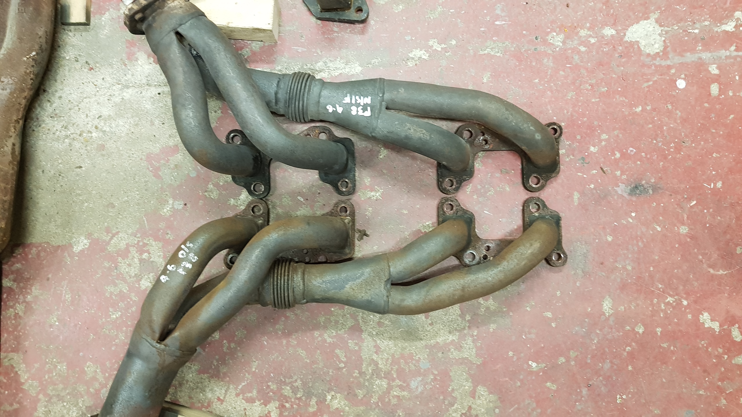
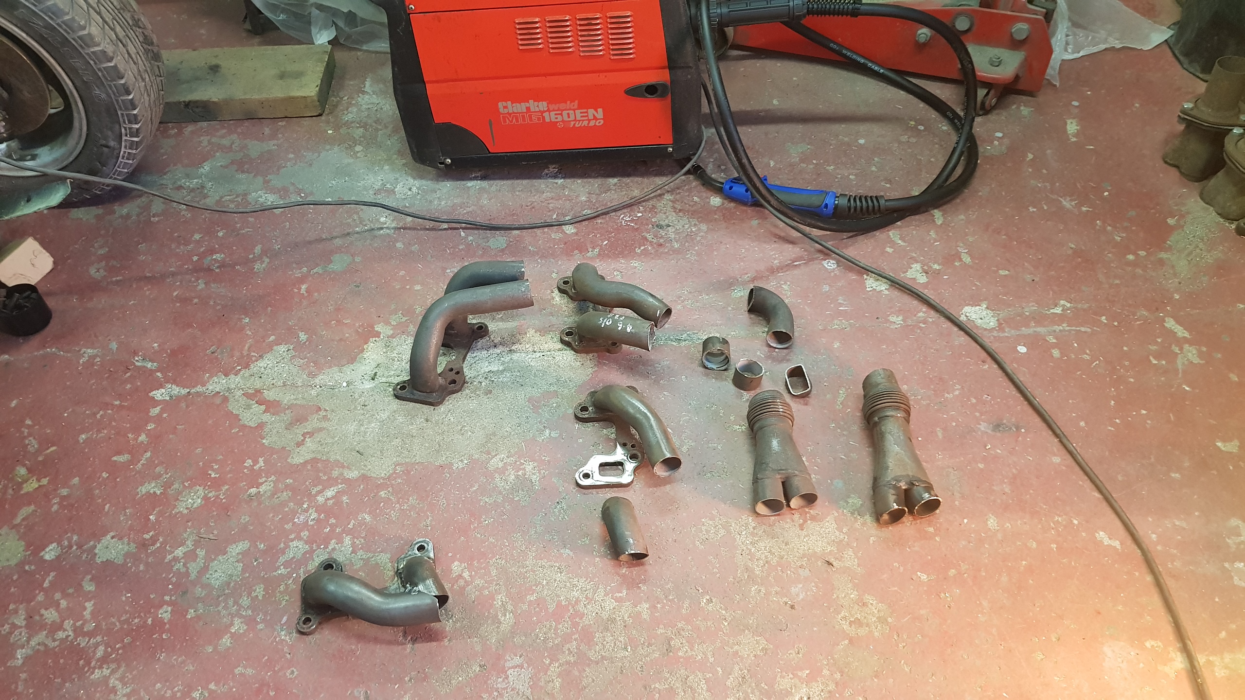
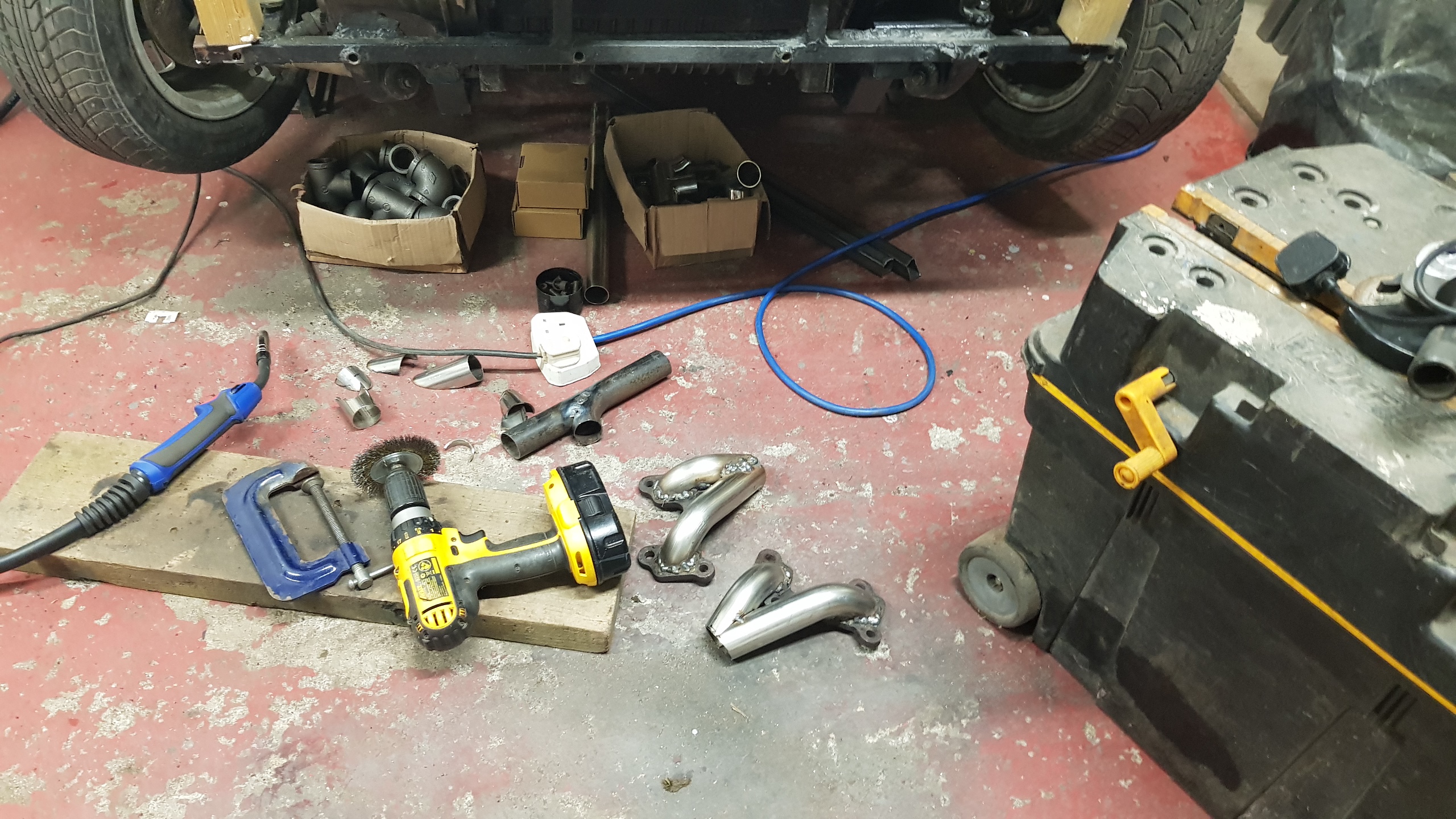
101 manifold on the left, along with some source material for the experiment. A set of Headman headers (rear) and a pair of Range Rover P38 at the front.

I think there's potential here starting with the front bit of each bank (at the right of the pic).
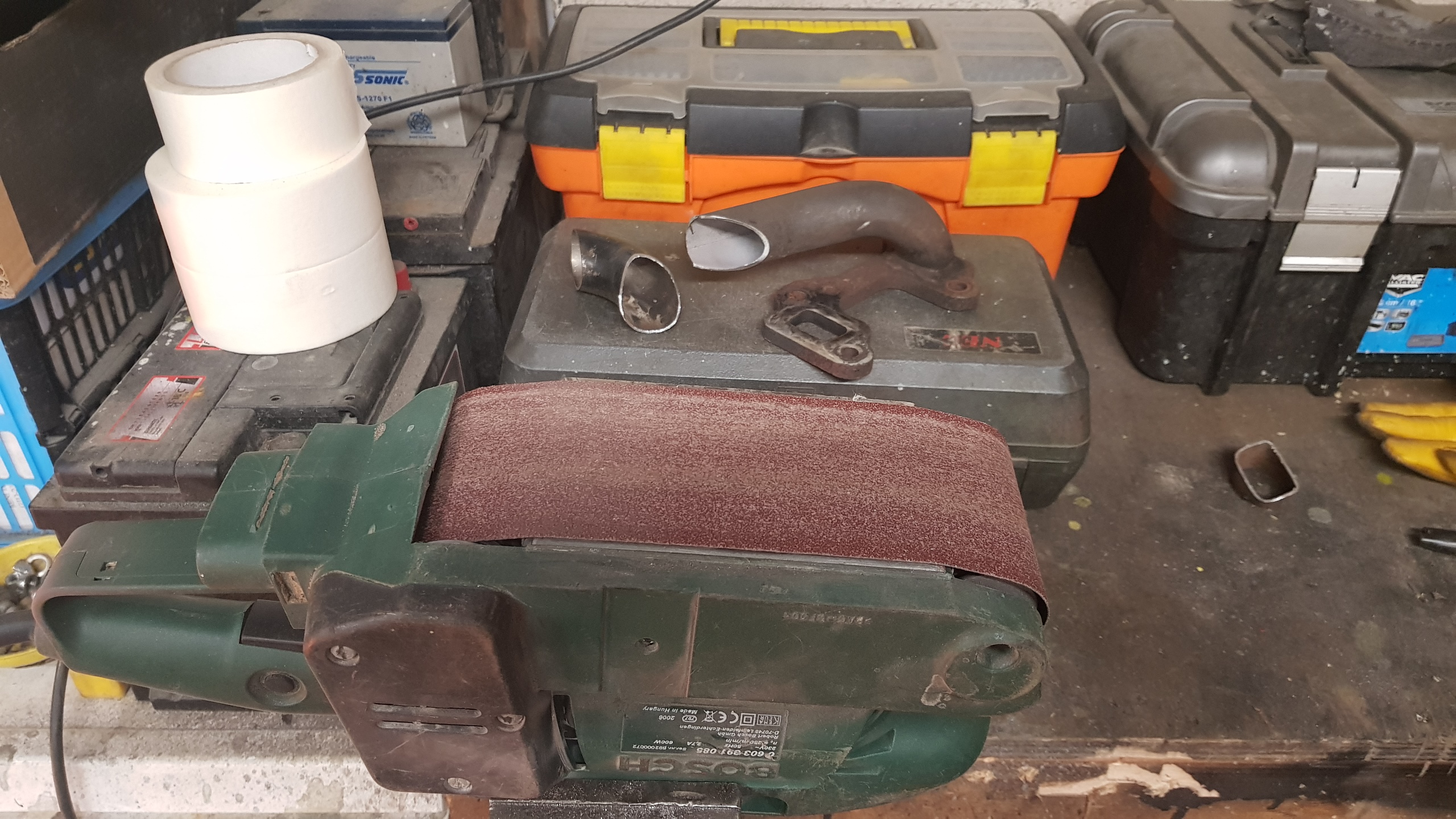
After chopping stuff, the bench grinder is great for profiling the cuts. It'd definitely not a belt sander in a vice - honest.
Another easy 3d jigsaw puzzle ?
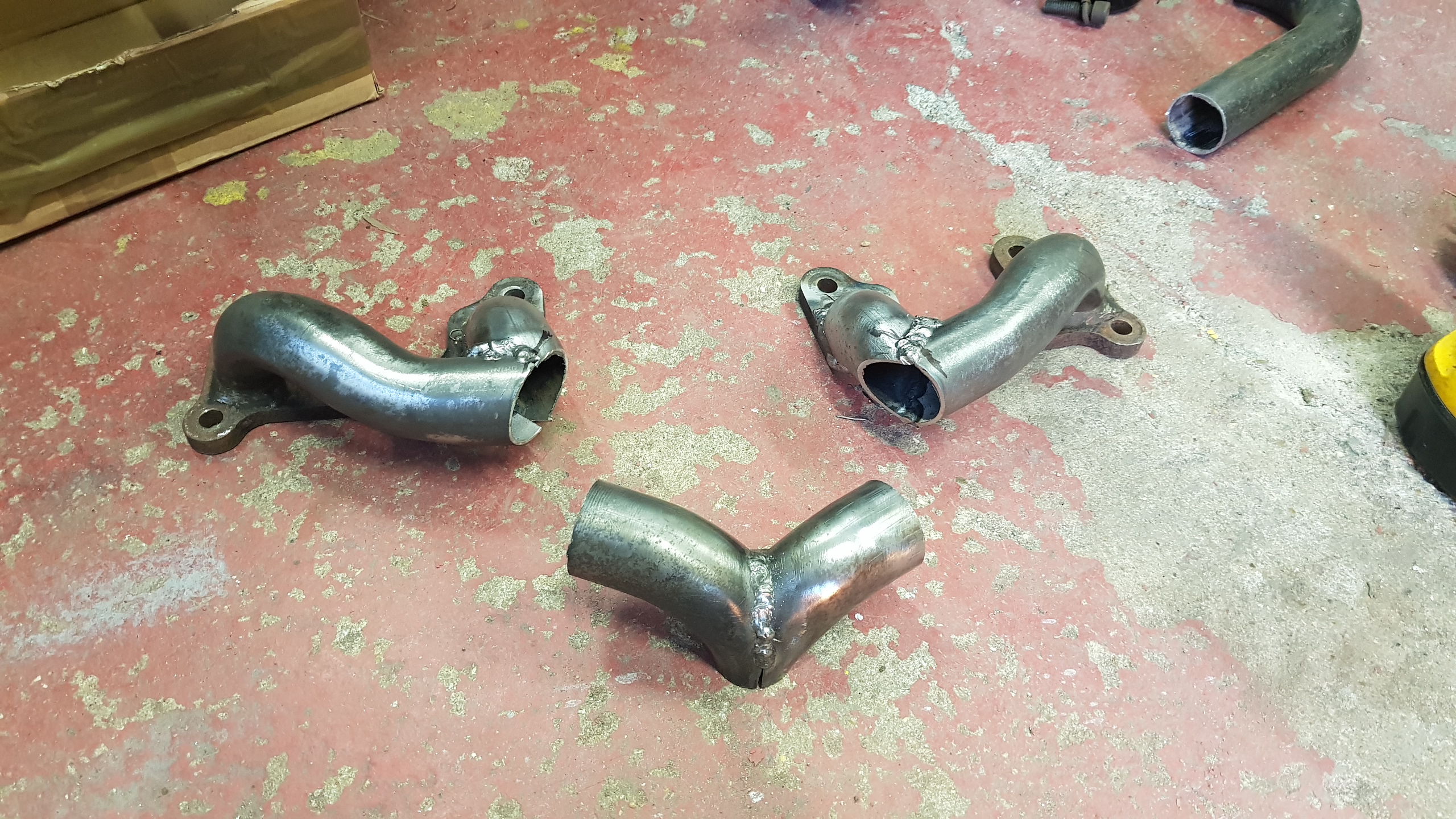
The first bit sort of fits, so just neet to make another port runner and join them all together.

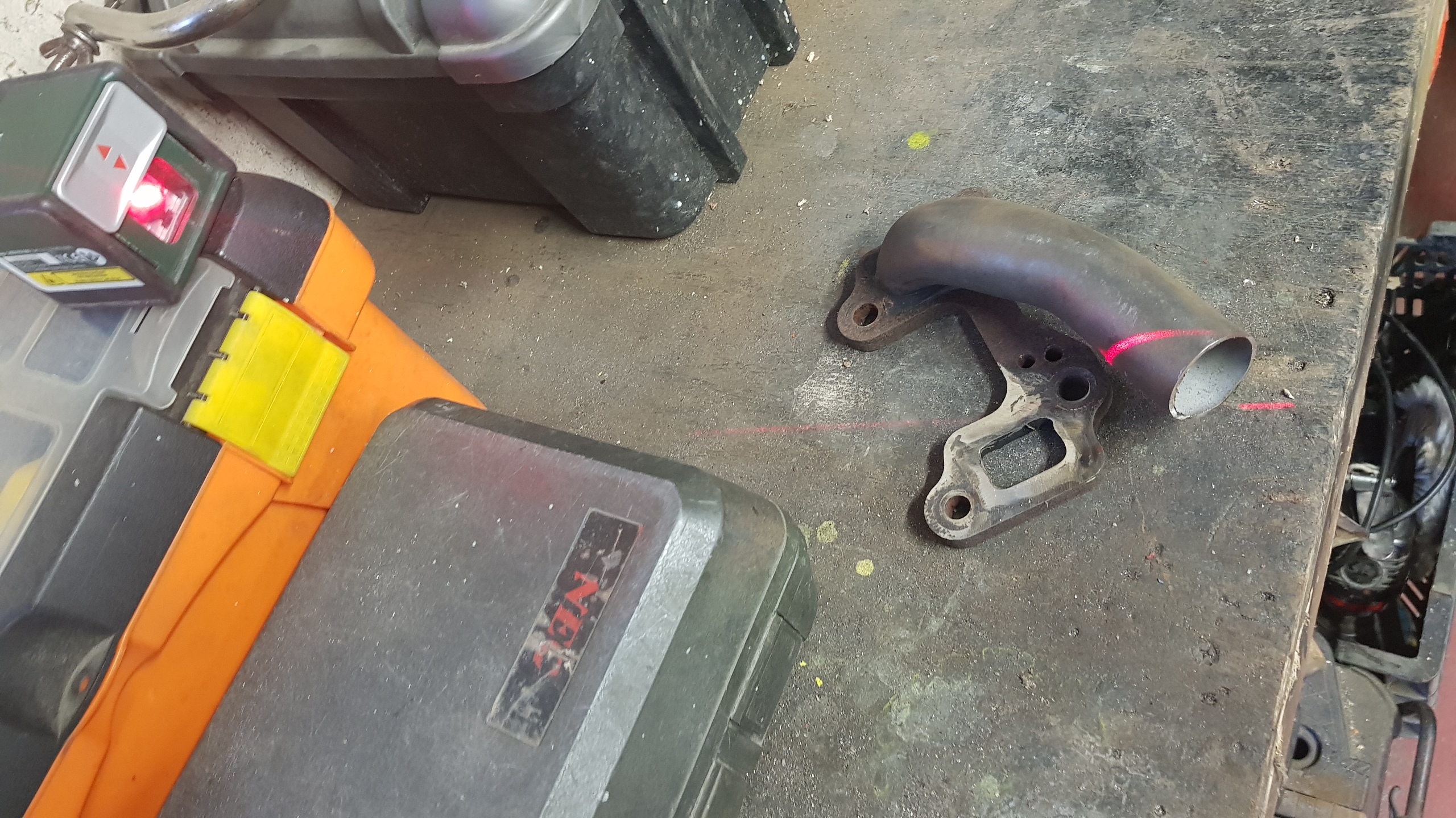
Just need to chop this bend to fit the flange and then match the two pipes together.
Chopping mostly done by eye, with a little help from the laser level to visualise some of the lines.
Ready to weld.

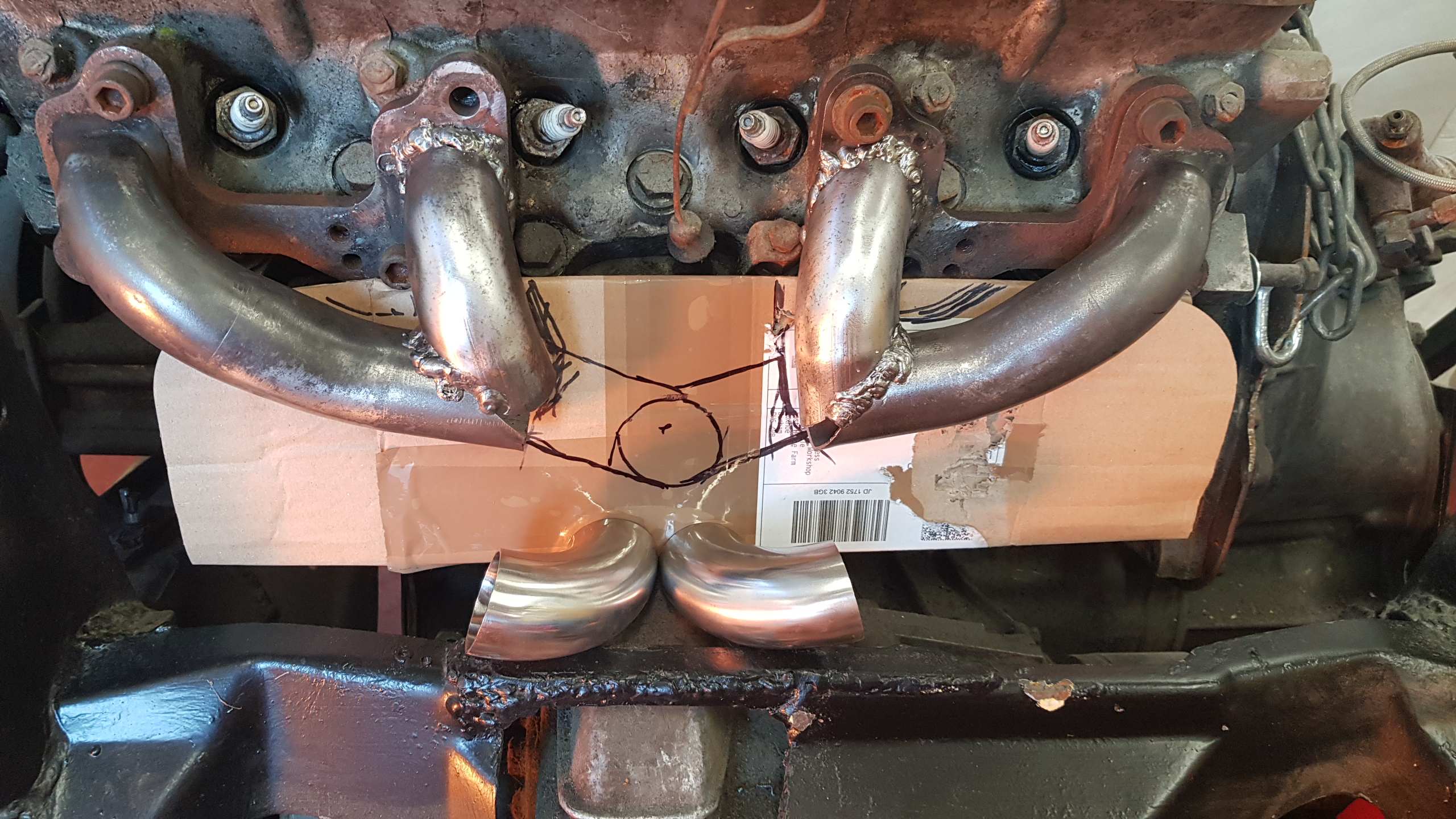
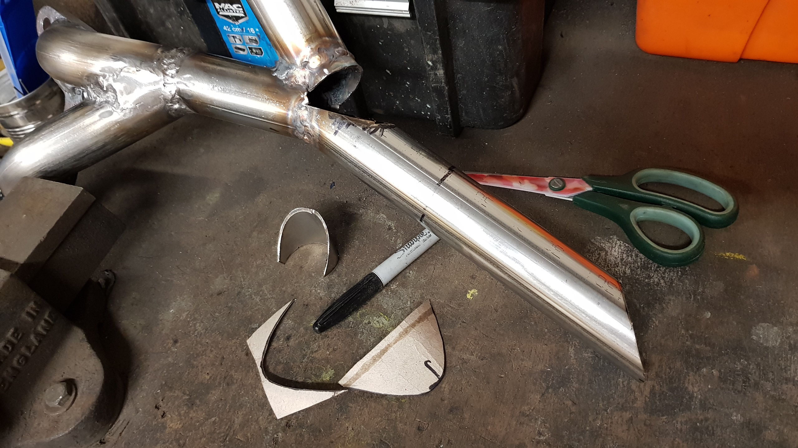
With the primary branches in place, I need to work out the angles for the next merge. This one is a bit more compliceted, so I had to resort to scribbling on cardboard..
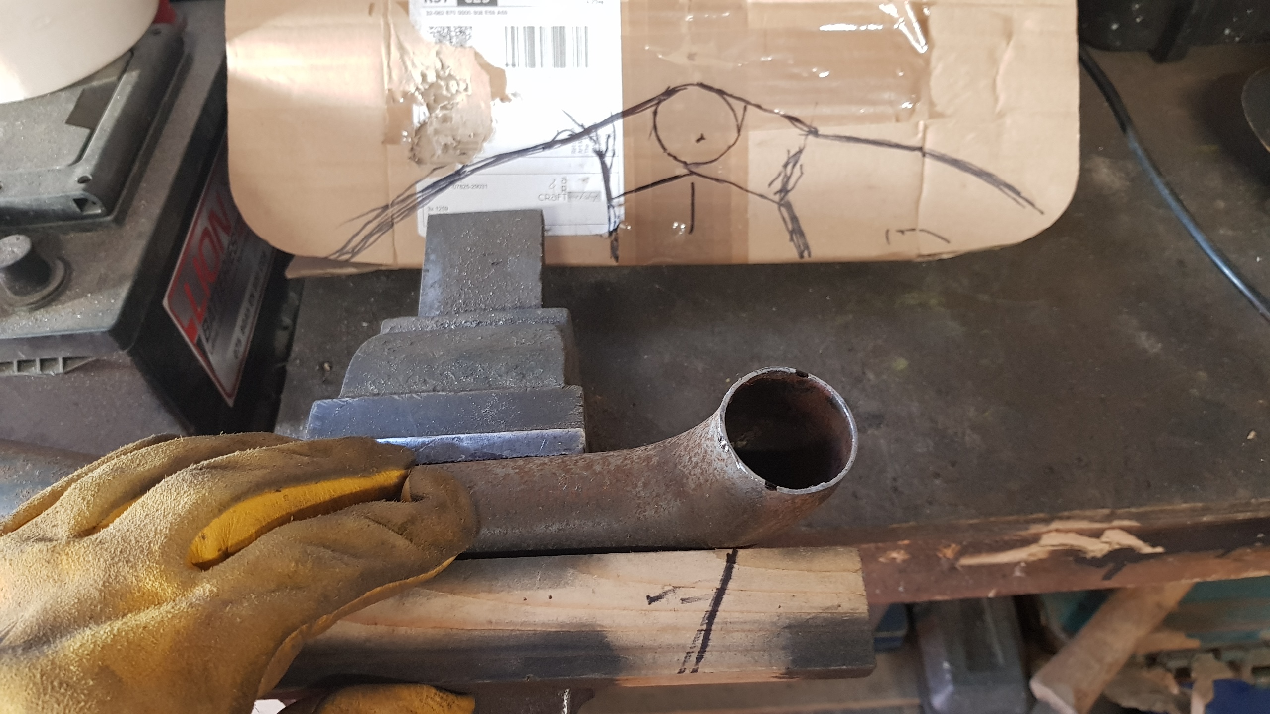
High tech 'bit-o-wood' angle transfer system in action for the cut lines.
This should do.
Chop these where they touch and tidy the edges a bit.
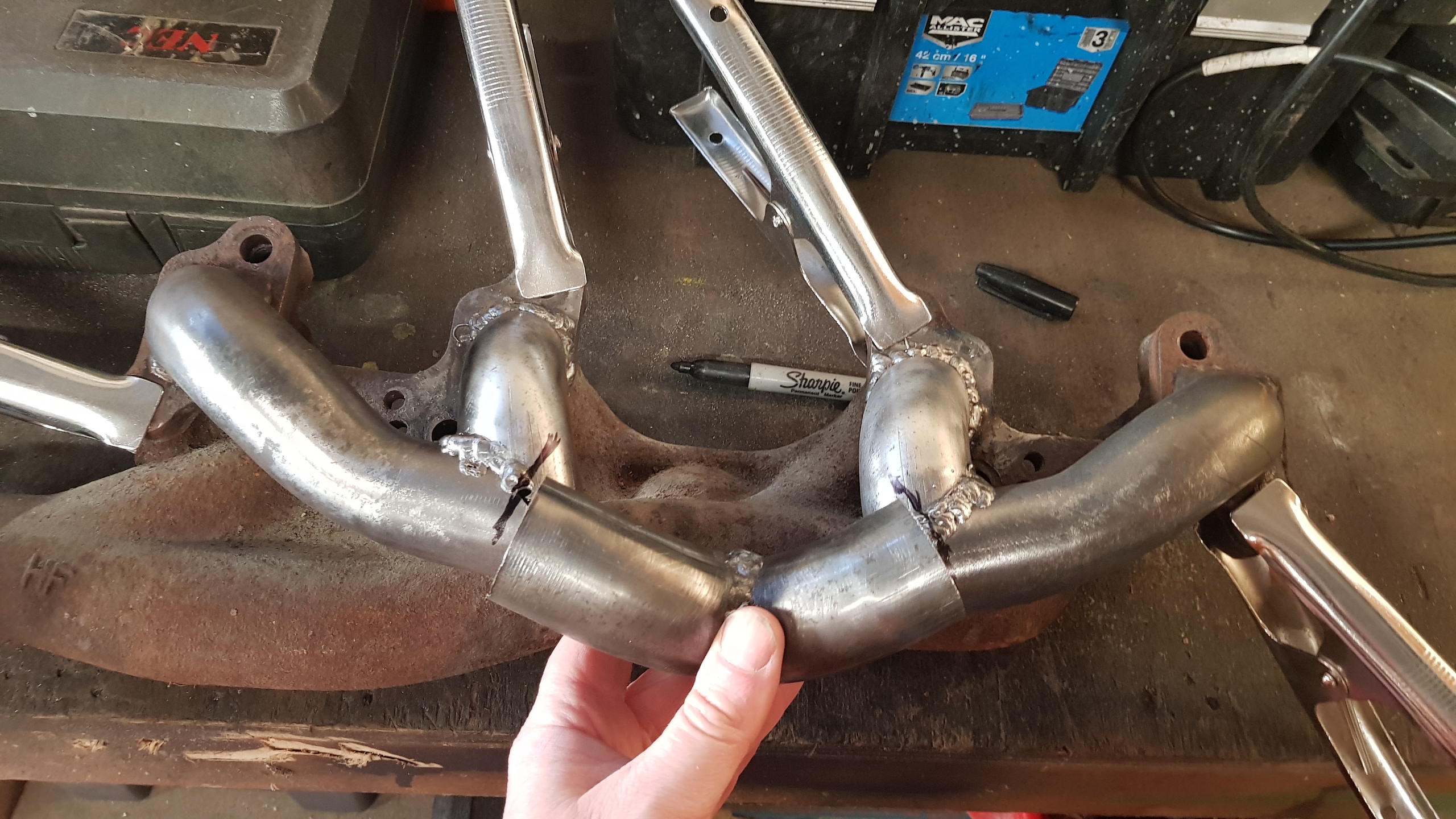
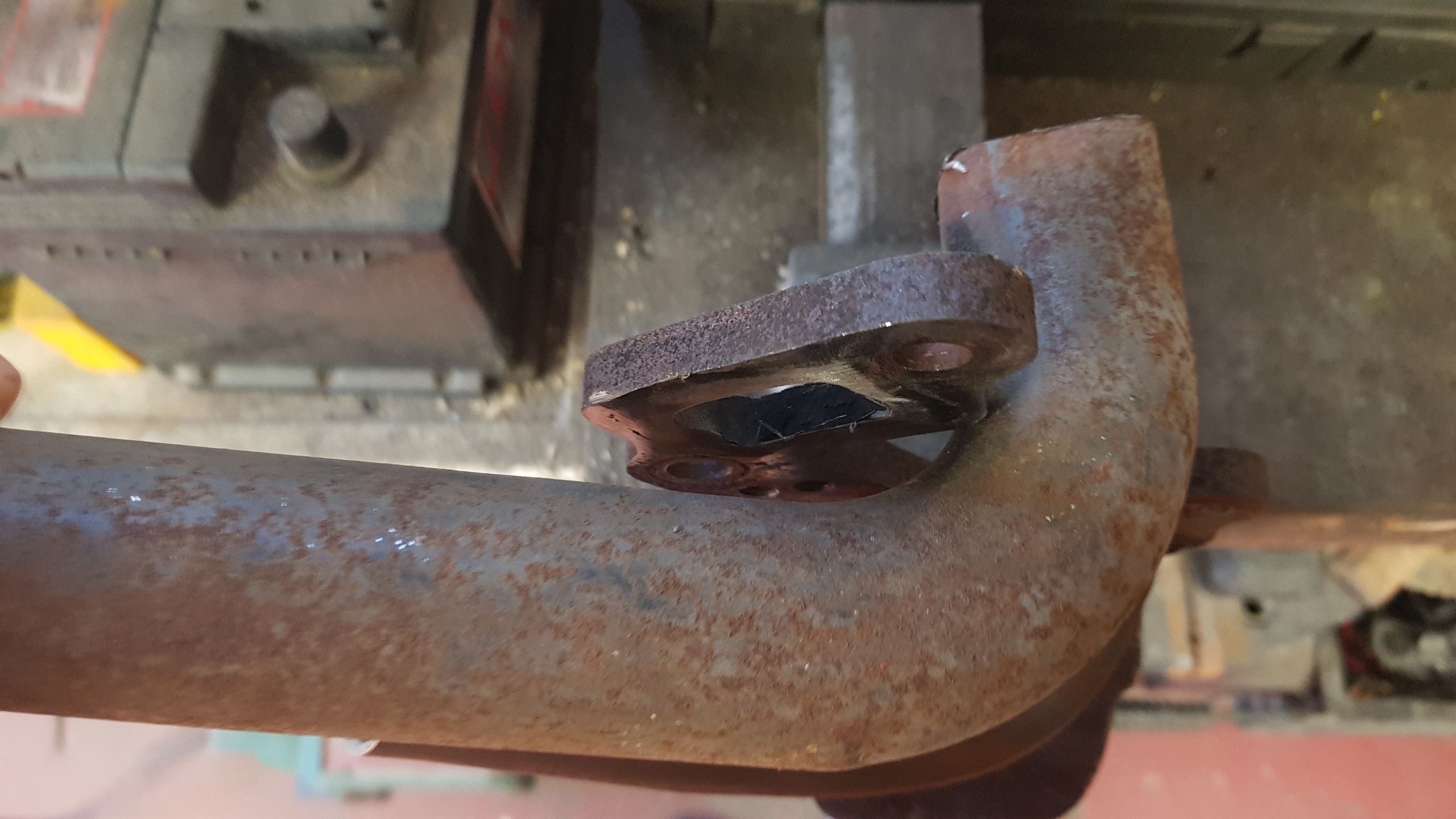
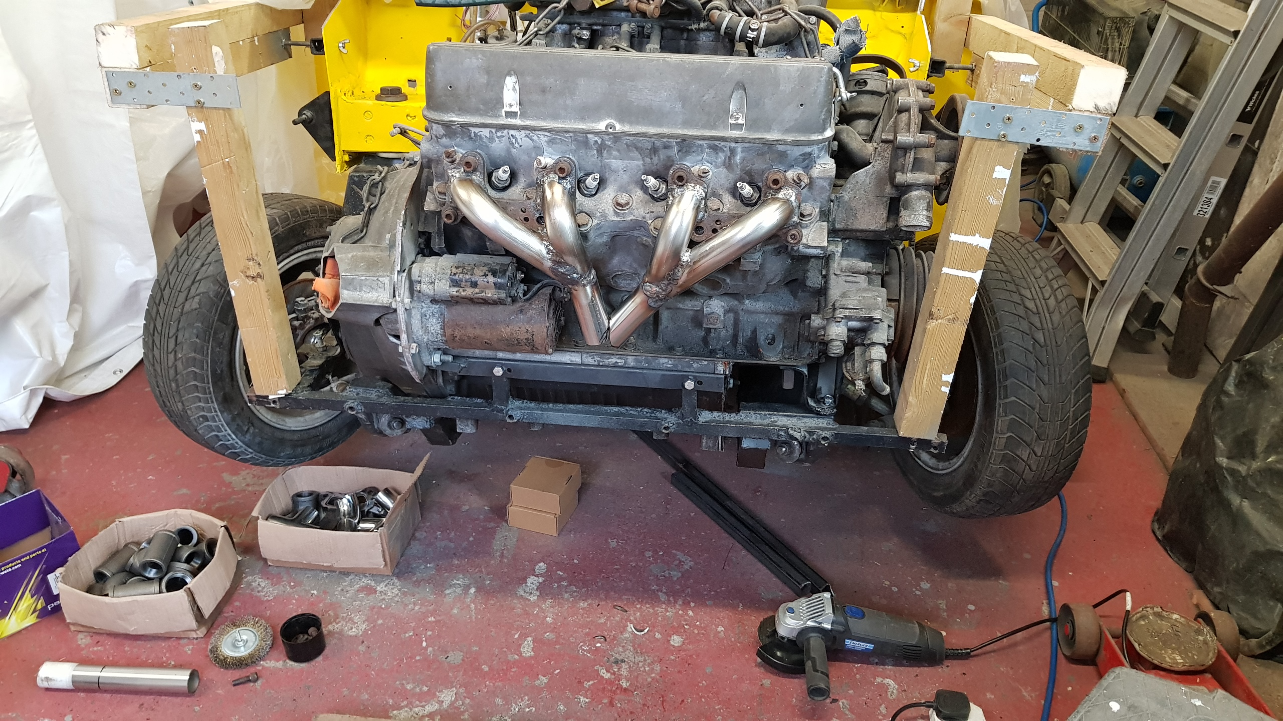
Bolt the flanges to the head and tack weld. Then remove from the head and glue it all together, finally adding the 100ish degree bend that brings it out ready for a 90 down past the diff...
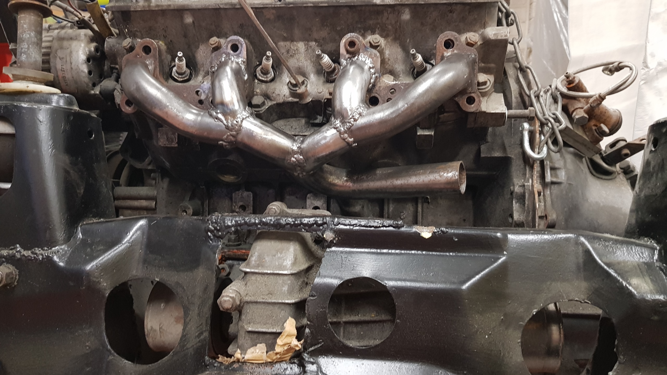
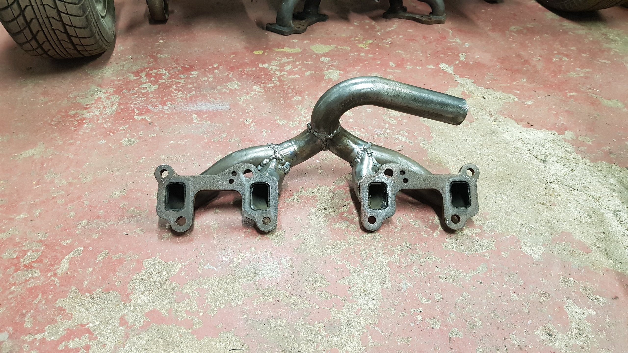
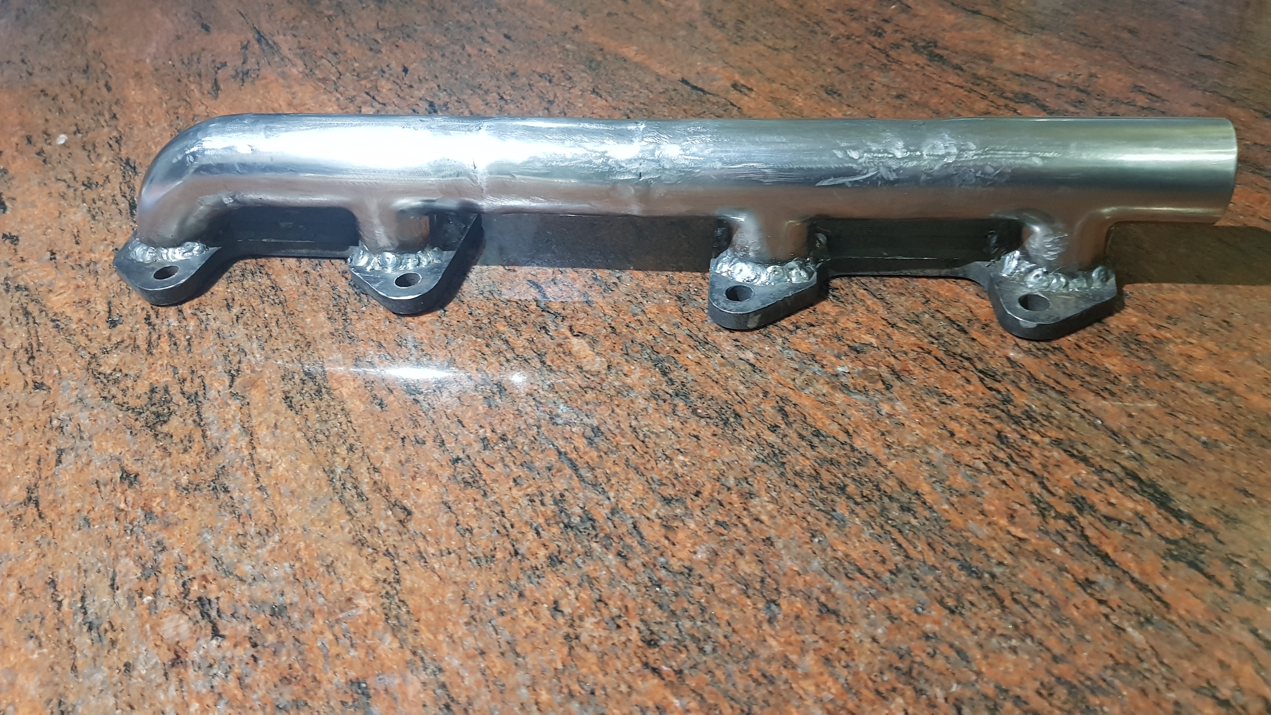
Looking shiny after a bit of love from the die grinder and the DA sander.
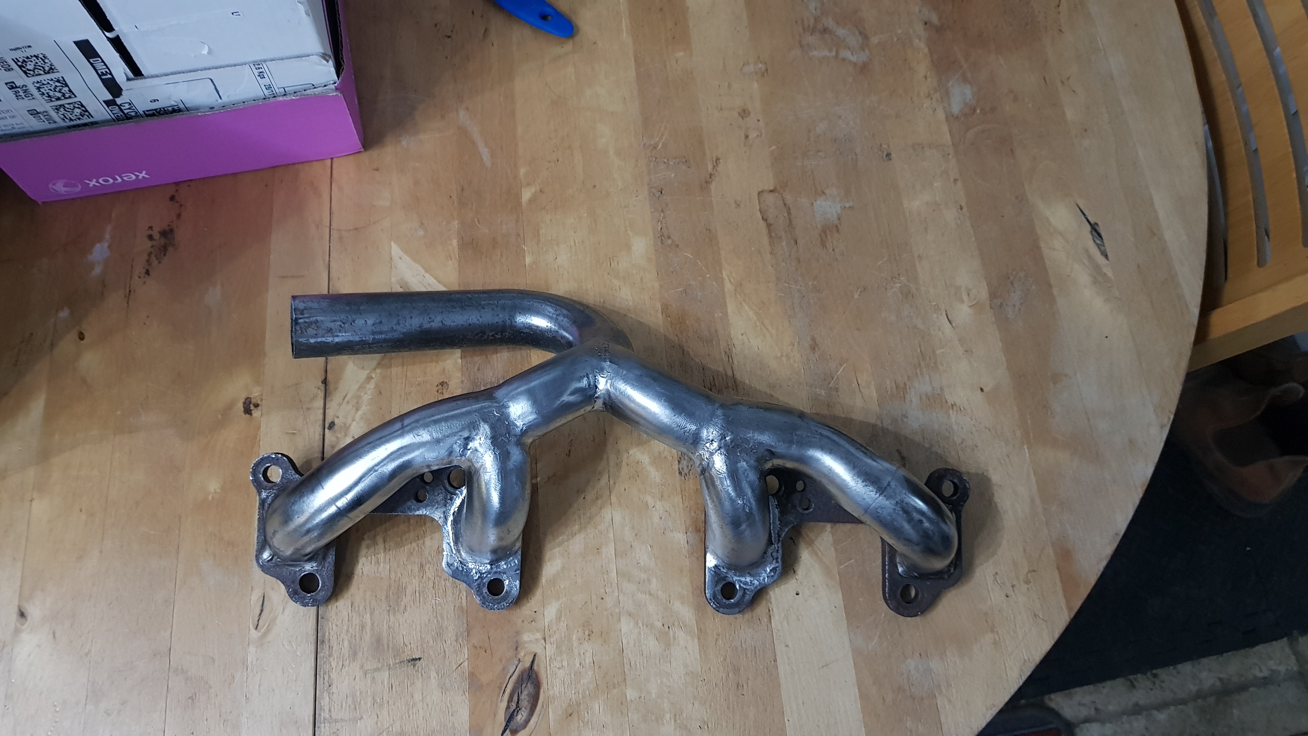
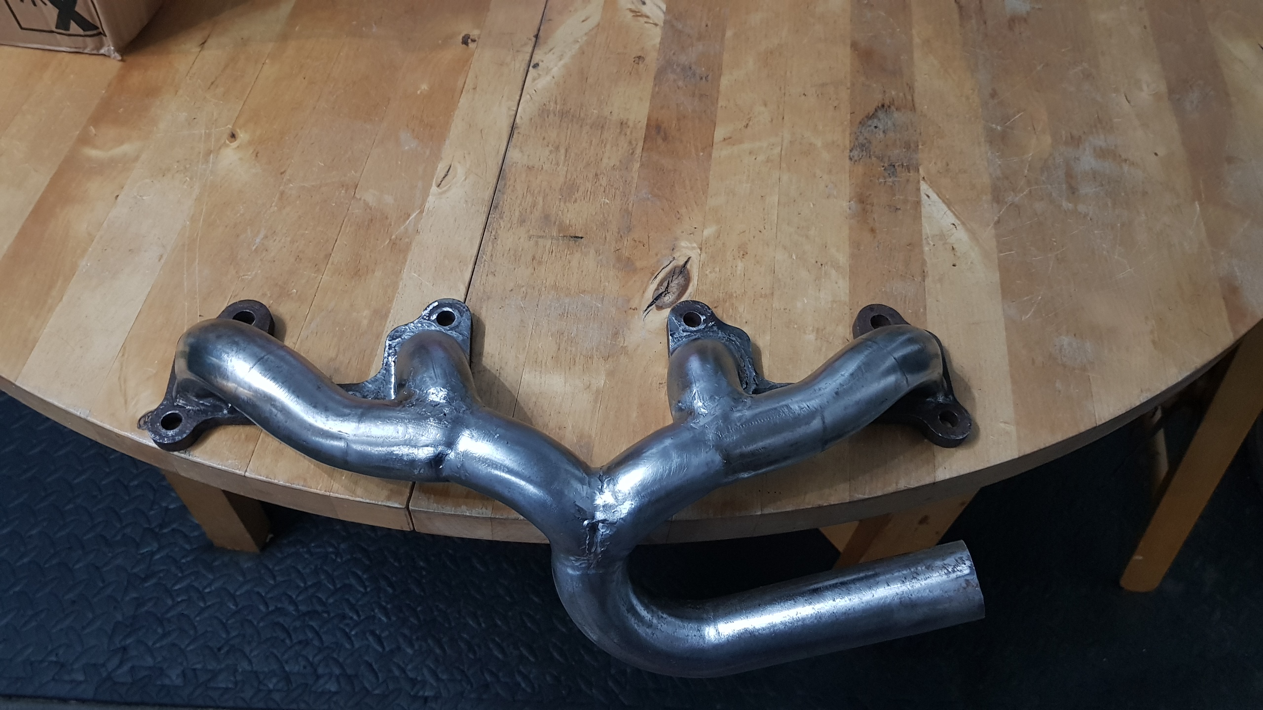
All in all it was a whole lot easier to just put together on the fly, rather than to try to design it first, or visualise what went where.
So, having discovered that it's not a total nightmare to bodge together
something branchy, I decided to make something for the front bank as an
alternative to the earlier log attempt.
Recycled flanges with pipe bits cut from some 180 bends should make a good start point.

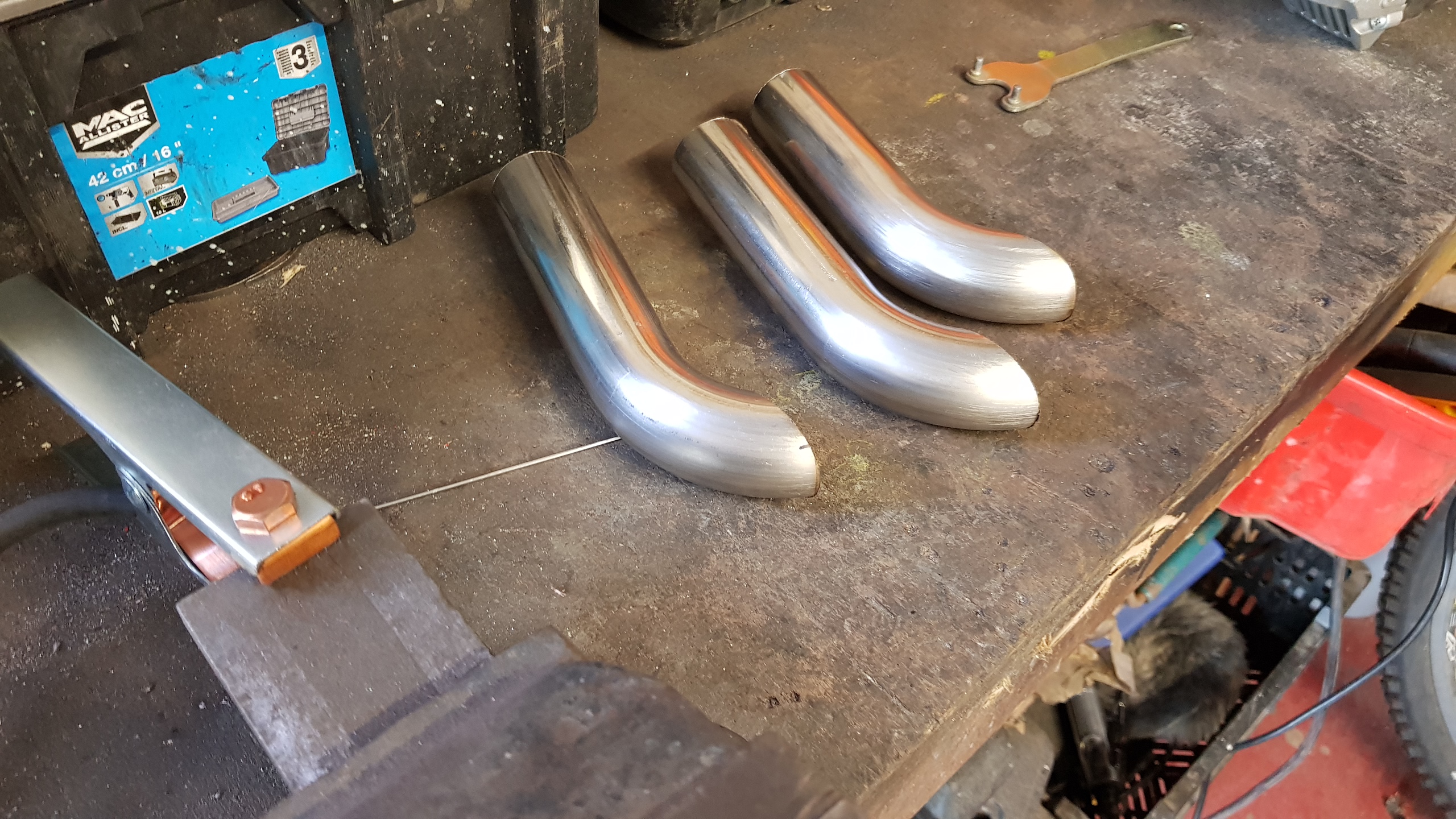
Rough cuts and rough tacking to get things roughly in place.
More chopping and fettling to get pipes to point the right way

I messed up the cutting, so need to fill a little gap...
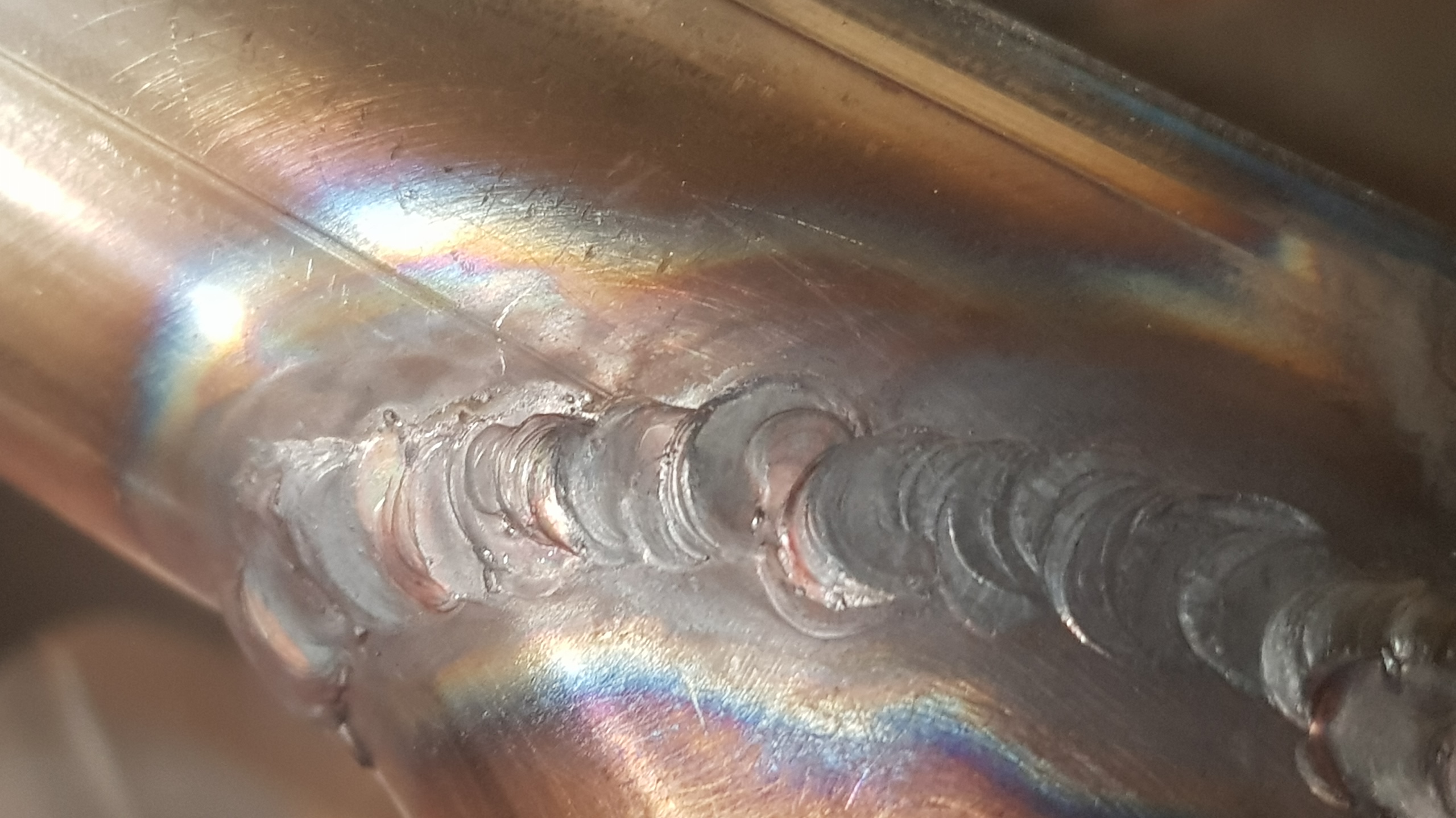
The TIGging isn't pretty yet, but it's getting less ugly :)
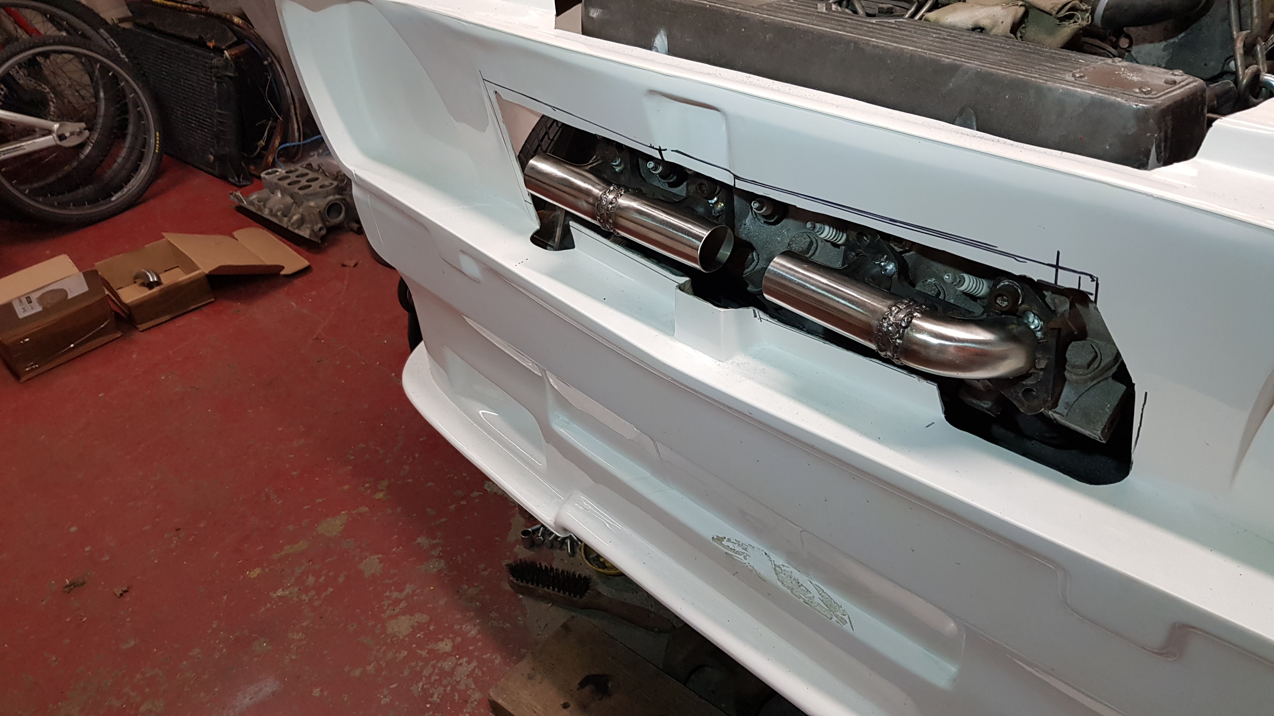
The manifold looks OK with the front fitted