
|
|
|
|
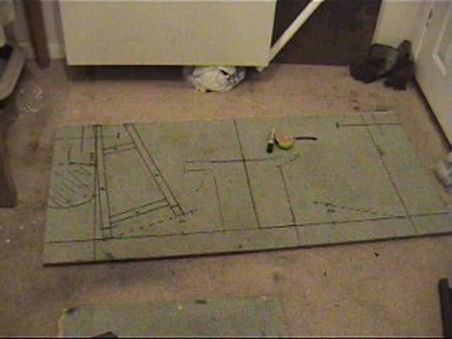
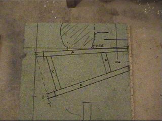
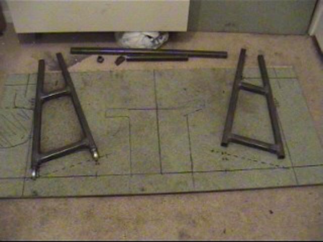
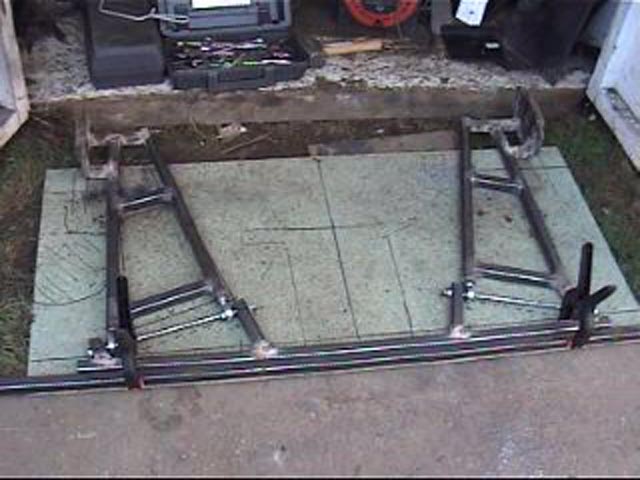
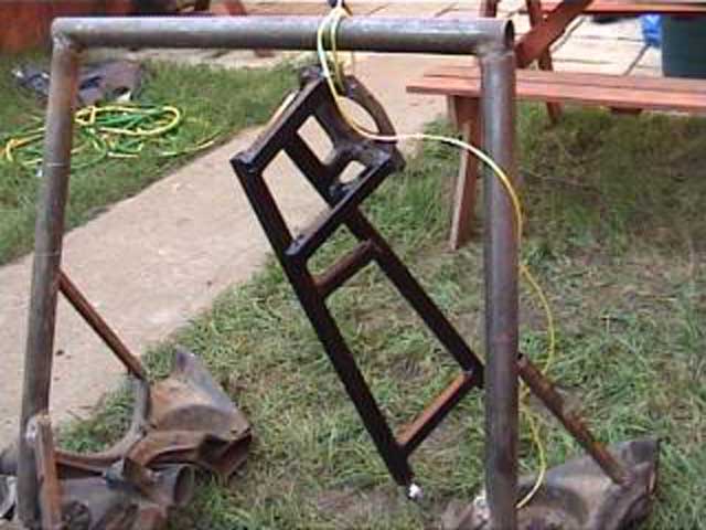
06/02/04 After building the subframe based on the Sierra axle, I was not really that happy with the look of the thing, so I decided that it was time to have a go at building one from scratch instead !! I measured the locations of the hubs and pivot points and transferred this to a big bit of chipboard, then I put a block in position and drew around that. From that the outline of the swing arms almost designed themselves !
The main sections of the arms are 25x25mm, 3mm thick box steel. Funny how easy it is to cut the right shapes when you use a 1:1 drawing !!!
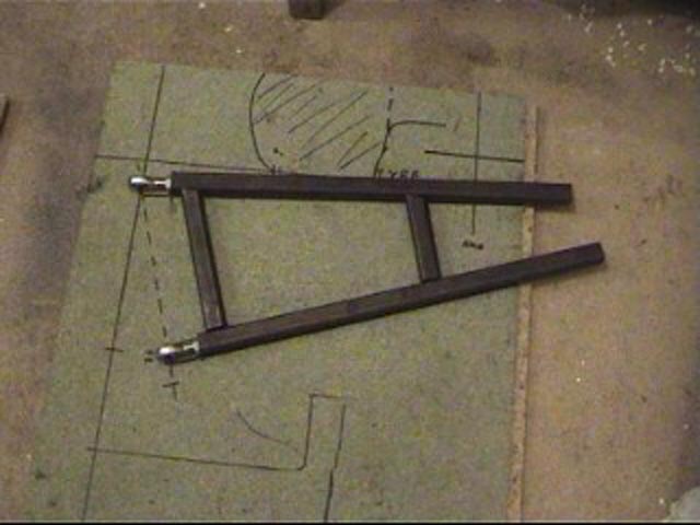
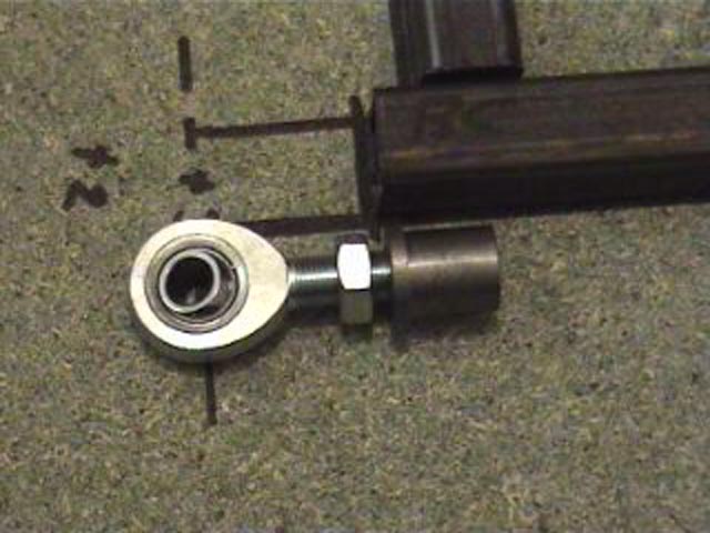
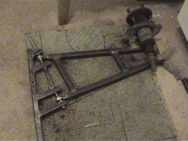
The pivots are nice rose jointed rod ends - not ideal for high mileage road use, but are not too expensive and will be very easy to change. The threaded inserts needed a bit of filing and quite a lot of hammering to 'press' them into the ends of the box before finally welding them in !
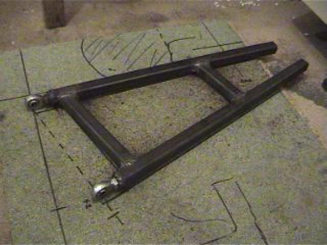
After a bit of welding the arms are starting to look quite solid.
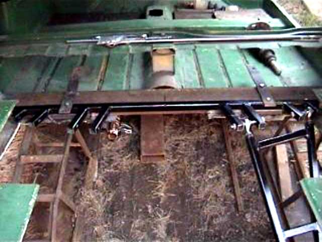
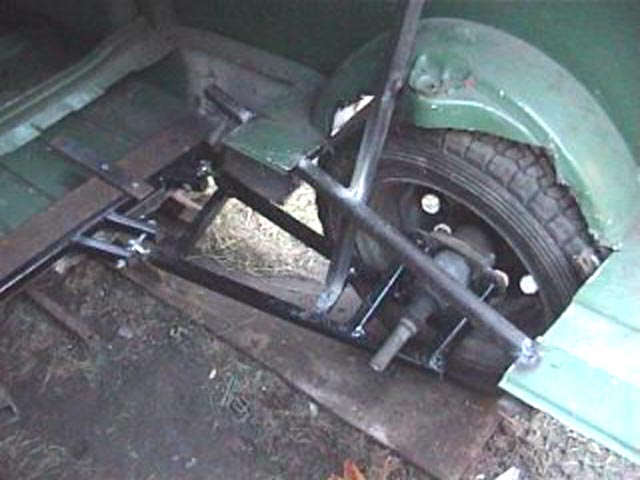
With the arms aligned using the markings on the board the pivot brackets were welded to another length of box section. (Yes, I know it's not very strong, but it will get welded to the back of the 50x100mm cross member already in the van!). Then with the arms attached, the hub ends were cut off of the Sierra arms and welded in place.
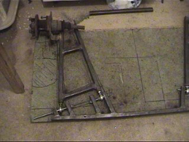
Additional inner pivot brackets will provide strong secure mountings for the rose joints. The Sierra bearing carrier just bolts into the end of the arm, so it would be easy to nick the disk brakes & hubs from a Saphire if the drums aren't up to the job ;-)
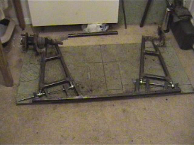
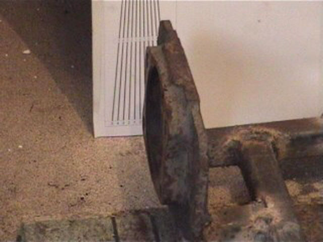
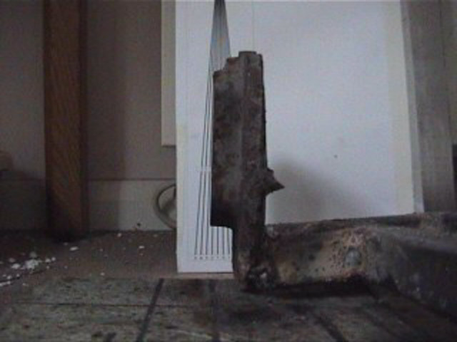
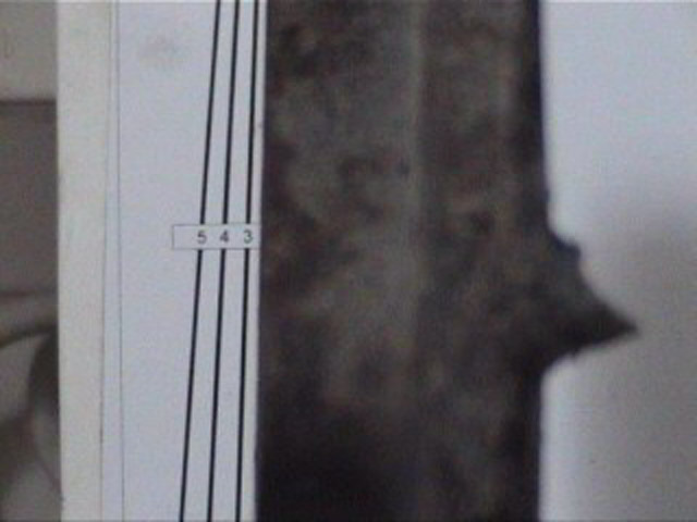
On each arm, the inner pivot point is set slightly behind the outer one to create a semi trailing arm. This means that as the suspension compresses and the hub 'rises' the amount of negative camber will increase. The idea behind this is that when the body rolls during cornering, more neg camber is added to keep a good tyre contact. While it's all off the car it's easy to use a printed camber gauge and tape measure to check the camber at different heights. 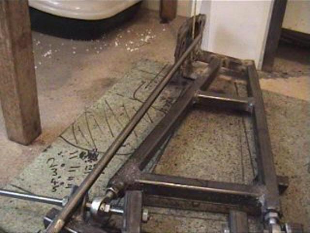

The angles have been set to give 2.5º at normal ride height increasing to 5º at 135mm compression (when the tyre hits the arch !!!)
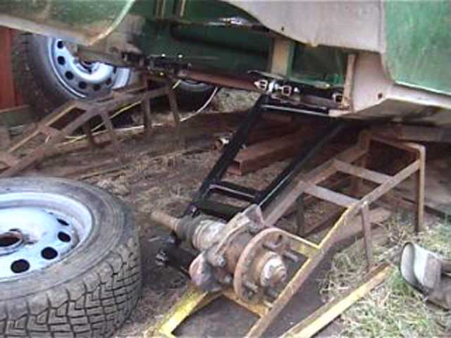
With the final angles set, some more bracing was added to support the hub, and a lick of black Hammerite was added
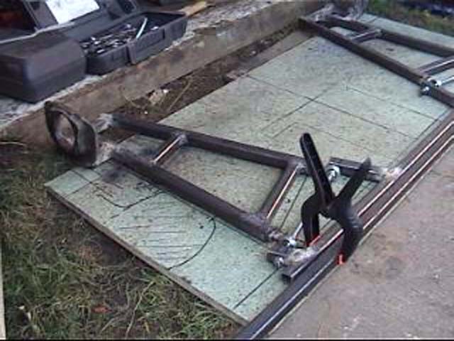
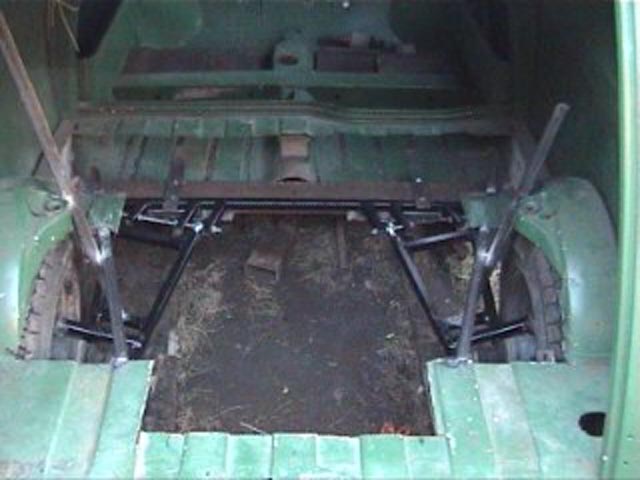
Trial fit of the brackets & arms in the van.
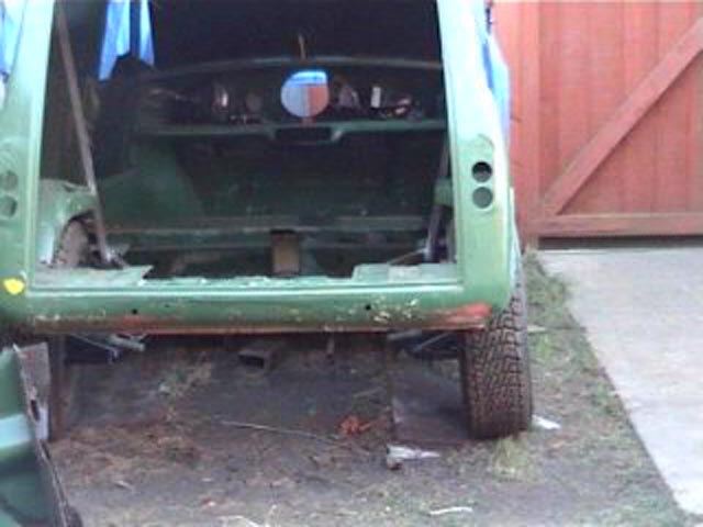
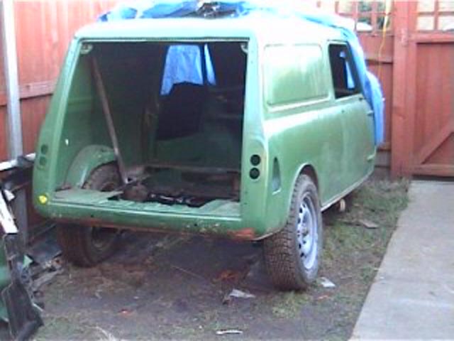
Then it was a simple job to bolt on the wheels and let the van touch down for the first time in several months !
Hmm, lots and lots of space for engine & stuff.
But I may need to finalise the suspension ;-)
|
|
NOTE AVI files compressed with the DivX codec, free from www.divx.com Diy
fuel injection by MEGASQUIRT For General V8 info try http://www.v-8.org.uk/forum/ For sensible Spag stuff visit www.spagweb.com or for madtech mayhem try www.magicspanner.co.uk
Looking for more Mini info ? Then try the Internet Mini Encyclopaedia www.ime.org.uk
Norfolk n Goode Pies, Your Favourite Farmyard Faces In Tasty Pastry Cases. http://www.norfolk-n-goode.co.uk
This page last modified 08/01/2008. |
 www.msefi.com